YOU'RE HEARD, LOUD AND CLEAR. Installation and Operation Manual for T-Pass® Transmit Multicouplers 73-90-11 Series Manual Part Number 7-9100 8625 Industrial Parkway, Angola, NY 14006 Tel: 716-549-4700 Fax: 716-549-4772 sales@birdrf.com www.bird-technologies.
Warranty This warranty applies for five years from shipping date. TX RX Systems Inc. warrants its products to be free from defect in material and workmanship at the time of shipment. Our obligation under warranty is limited to replacement or repair, at our option, of any such products that shall have been defective at the time of manufacture. TX RX Systems Inc. reserves the right to replace with merchandise of equal performance although not identical in every way to that originally sold. TX RX Systems Inc.
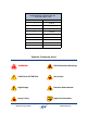
Manual Part Number 7-9100 Copyright © 2011 TX RX Systems, Inc. First Printing: March 1993 Version Number Version Date 1 03/05/93 2 05/10/93 3 01/24/94 4 07/08/96 5 10/17/11 Symbols Commonly Used WARNING ESD Electrostatic Discharge CAUTION or ATTENTION Hot Surface High Voltage Electrical Shock Hazard NOTE Heavy Lifting Bird Technologies Group Important Information TX RX Systems Inc.
Changes to this Manual We have made every effort to ensure this manual is accurate. If you discover any errors, or if you have suggestions for improving this manual, please send your comments to our Angola, New York facility to the attention of the Technical Publications Department. This manual may be periodically updated. When inquiring about updates to this manual refer to the manual part number and revision number on the revision page following the front cover.
Table of Contents General Description ........................................................................................... 1 T-Pass Selectivity vs. Cavity Loss ....................................................................... 4 Unpacking ............................................................................................................ 4 Installation Overview........................................................................................... 4 Assembly...........................
Figures and Tables Figure 1: Interconnect diagram of typical system ................................................ 1 Figure 2: Typical transmitter noise suppression ................................................... 3 Figure 3: Front view of 21 channel multicoupler ................................................... 5 Figure 4: Mounting rack detail .............................................................................. 6 Figure 5: Typical combiner installation .....................................
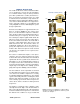
GENERAL DESCRIPTION The 73-90-11-NN Series T-Pass Transmit Combiners are designed to connect up to 21 transmitters to a common antenna. They use three-port bandpass filters (called T-Pass cavities) and ferrite isolators to provide low channel insertion loss, high isolation between transmitters, high antenna-totransmitter isolation, high intermodulation suppression, and excellent transmitter noise suppression.
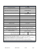
Specifications (Note 1) 73-90-11-2C-nn 73-90-11-2D-nn Frequency Range (Note 2) 806 - 960 MHz Cavity Type and Diameter 3/4-wave 6.625” (168 mm) Max Continuous TX Power @ Tx-Tx Separation 150 Watts @ 450 KHz 125 watts @ 250 KHz Isolator Load Power (Continuous) (Note 3) 5W / 60W 5W / 100W Minimum TX-TX Separation @ Cavity Loss 450 KHz @ -1.25 dB 250 KHz @ -1.80 dB Channel Insertion Loss See Table 2.
Channel Loss (dB) vs. Number of Channels Tx-to-TX Separation Cavity Loss (dB) 1 MHz 500 KHz -1.25 450 KHz 250 KHz -1.80 2 3 4 5 8 10 12 -2.1 -2.3 -2.4 -2.5 -2.8 -3.0 -3.3 -2.3 -2.8 -3.0 -3.2 -3.6 -3.9 -4.1 -2.4 -2.9 -3.2 -3.4 -3.9 -4.1 -4.3 -3.1 -3.8 -4.1 -4.4 -4.9 -5.2 -5.5 Table 2: Typical T-Pass Channel Insertion Loss. Note regarding Table 2: The typical channel losses specified here are for equally spaced channels only.
has been factory tuned in most cases so that no adjustments are necessary. The specifications for the 73-90-11-NN family of T-Pass combiners are listed in Table 1 and the typical T-Pass channel insertion loss is shown in Table 2. The response curve shown in Figure 2 shows the typical transmitter noise suppression. Noise suppression depends on the cavity’s loss setting. T-Pass Selectivity vs.
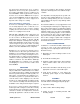
Antenna connects here TX 21 L21 TX 19 TX 20 L20 L19 TX 18 TX 17 L18 L17 TX 15 TX 16 L16 L15 TX 14 TX 13 L14 L13 TX 11 TX 12 L12 L11 TX 10 TX 9 L10 Transm itters connect to type N connector on isolator. L9 TX 7 TX 8 L8 L7 TX 5 TX 6 L6 L5 Isolator mounting clamp connector access hole on bottom for this bracket. Hole is on top for all other isolators. TX 3 TX 4 L4 First cavity has built-in short circuit.
4) T-Pass thruline cables and isolator to cavity cables. Peg-Rack Assembly If the unit was fully assembled then this step may be disregarded. A separate instruction sheet for the rack assembly is included with the rack. Cavity / Isolator Mounting After the Peg-Rack is assembled, the cavity filters are mounted. They are packaged separately from the isolator assemblies. The cavities have an identification tag attached indicating their frequency which is used to identify the cavity position in the system.
6) Similarly connect the T-Pass Thruline cables to the cavities using the THRULINE DATA Sheet and figure 3 as a guide. Four, 17/64" (6mm) diameter mounting holes are provided in the base for attaching the rack to the floor using bolts or lag screws. Caution: The Thruline cables must be installed in the correct location for proper operation. Use pliers with rubber jaws to tighten these connections slightly more than finger tight.
It is advised that the center pin on all mating N male connectors be checked for proper alignment before connection to the multicoupler. A cocked center pin in the male connector can permanently damage the mating female connector. In many cases, simple field replacement of the damaged connector is not possible and replacement of an entire subassembly may be required to make the unit operational. This system is designed for use with separate transmit and receive antennas.
a corroded tower joint, metal-roofing, transmitter final amplifier or the receiver front-end. Both cavity filters and ferrite isolators isolate the transmitters connected to the combiner from oneanother thus reducing intermodulation interference. However in all transmitter combiners, intermodulation products are reduced in strength but never completely eliminated. They have to be reduced by an amount to meet the Federal Communications Commission, 43 + 10 Log(Power Out) rule for spurious output reduction.
For a Power Out (P O ) of 45 watts and a Power Input (PI) of 105 watts: Loss (dB) = 10 Log10 (45/105) Loss (dB) = -3.7 For a PO of 55 watts and PI of 95 watts: Loss (dB) = 10 Log10(55/95) Loss (dB) = -2.4 So the calculated loss for this channel can run from -2.4 to -3.7dB and be acceptable considering the measurement error factor. The actual error could be much greater if a 250 watt element was used; the measured values could vary by as much as +/12.5 watts.
MULTICOUPLER TUNING T-Pass transmitter combiners are pre-tuned at the factory and usually require no adjustment. T-Pass expansion channels are also pretuned but may require fine tuning after being installed in an existing system. Channels that are close in frequency (adjacent channels in the multicoupler) to the expansion channel may also benefit from fine tuning due to the slight interaction that occurs with the new channel.
Fine Cavity Tuning Figure 7 shows a hookup suitable for fine tuning any channel under power while installed in the multicoupler. The term fine tuning here refers to cavities that have already been tuned to frequency and may only require adjustment of the fine tuning control (+/- 50 KHz). The transmitter is used as a signal source and the cavity is adjusted for minimum reflected power.
Spectrum Analyzer Bird SignalHawk Coarse Cavity Tuning Wh en a T-Pass c avi ty fr equ enc y has t o b e changed by over 50 KHz, adjustment of the main tuning rod is required. Large frequency changes are more easily observed when using a tracking generator and a return loss bridge to give a swept display of the return loss curve. The return loss curve is a very precise indicator of T-Pass cavity tuning.
Small movements of the main tuning rod are facilitated by tapping the rod with the handle end of a screw driver while gently pushing or pulling the main tuning rod. 6) Lock the Main and Fine tuning rods and reinstall the cavity in the system. Use the previously outlined fine tuning procedure to verify proper tuning under power.
should be positioned as shown in figure 10. Do not tighten the clamps. 6) Rotate the isolator mounting bracket so that the isolator is in the vertical plane as illustrated, forming a smooth line in relation to the other channels in the rack. 7) Due to the limited space, tightening may require the use of a 5/16" open end wrench. Tighten both clamps securely. 8) Connect the isolator-to-cavity cable. Use a pair of cable pliers to tighten-up the connectors.
cavity selectivity which may be necessar y to accommodate more closely spaced channels. Changing the loss is accomplished by rotating the coupling loops to change the coefficient of coupling. Both loops are normally adjusted for a given insertion loss setting. Most T-Pass cavities have a Calibration Index label beside both loops that gives a relative indication of their settings (see Figure 11). In actual practice, these marks are not accurate enough for setting loss values consistently.
short circuit. This loop is only used once in the bottom cavity of the T-Pass stack. Detailed procedures and illustrations follow on the next few pages. 5) UG-914/U, BNC(F)-BNC(F), union. TX RX Systems' part # 8-5805. CAVITY LOSS SETTING PROCEDURE 1 This procedure uses precision rotary attenuators, a signal generator and an RF Millivolt meter. 7) UG-57B/U, N(M)-N(M) coupling. 6) UG-28A/U, N(F), N(F), N(F) tee. 8) Two, UG-201A/U BNC(F)-N(M) adapter. TX RX Systems' part # 8-5814.
tors for the Reference Notch Depth Value shown in the chart (table 4) for the desired insertion loss and T-Pass loop part #. 2) Connect the test leads together through the female union, as shown in Figure 12, and adjust the range switch and the zero set on the voltmeter for a convenient reference level (A level of 2 on the 0 to 3 scale for example) on the meter. The generator output level may also be adjusted slightly if necessary.
Modulated Signal Source RF Voltmeter UG-28A/U UG-57B/U Bandpass Loop 50 Ohm Adaptor 10 dB Pad 10 dB Pad 0.1 dB/Div. 1.0 dB/Div. 10 dB/Div. Rotary Attenuators Set to Loop Reference Settings Small Circle on Bandpass Loop indicates ground end of loop and should be oriented as shown. Previously calibrated T-Pass Loop 3-1268 short circuit removed. Figure 14: Setting the Bandpass loop using step attenuators.
tor output level may also be adjusted slightly if convenient. Required Test Equipment 1) Spectrum Analyzer and a signal generator. 3) Set all three attenuators for 0 dB but leave them in the circuit. 2) Two 10 dB fixed attenuator pads with BNC connectors. JFW Industries model 50F-010. 4) Connect a UG-107 Tee and the UG-57B/U to the Bandpass loop as shown on figure 14. Then connect the test leads as shown. Make sure the short circuit stub has been removed from the TPass loop.
Signal Generator UG-28A/U UG-57B/U T-Pass Loop 10 dB Pad 10 dB Pad Short Circuit Connector 3-1268 from top of rack Bandpass Loop turned upside down with connector inserted into cavity. Loop visible and screws tight. Spectrum Analyzer Bird SignalHawk Figure 15: Setting a T-Pass loop for a specific cavity insertion loss. 7) Temporarily connect the test leads from the spectrum analyzer together through a UG-914 BNC union to set the zero reference.
Signal Generator UG-28A/U UG-57B/U Bandpass Loop 10 dB Pad 10 dB Pad Small Circle on Bandpass Loop indicates ground end of loop and should be oriented as shown. Previously calibrated T-Pass Loop 3-1268 short circuit removed. Spectrum Analyzer Bird SignalHawk Figure 16: Setting a Bandpass loop for a specific cavity insertion loss. and let it warm up for at least 30 minutes if this has not been done. 7) Connect a UG-28 tee and a UG-57 coupling to the bandpass loop as shown in figure 16.
11) Tighten all loop locking screws. The cavity loss is now set. The cavity will have to be tuned to its operating frequency following the procedures outlined earlier in this manual. MAINTENANCE Because T-Pass transmitter multicouplers are composed of mostly passive components, they will continue to operate without any maintenance for years and there is no recommended maintenance period.
Appendix A 800 MHz Isolators (Compact Style) GENERAL DESCRIPTION Isolators perform two important functions. Their primary function is to keep other RF frequencies out of the transmitter so that intermodulation products cannot be generated. Isolators have a substantial amount of reverse isolation. They also insure that the transmitter never sees any significant reflected power so it will always operate with maximum stability at full-power output.
INSTALLATION The isolators can be mounted on most types of surfaces but should not be physically located where they will not be exposed to moisture or very high humidity. TXRX Systems isolators are well shielded magnetically and may be mounted on steel cabinets or panels. The isolators can get quite hot during operation. This can occur when an antenna system component fails causing high reflected power which is then dissipated by the isolator load.
Spectrum Analyzer Bird SignalHawk Spectrum Analyzer Bird SignalHawk Tracking Generator Tracking Generator 50 Ω Load 50 Ω Load Figure A1: Verifying Reverse Isolation. TX RX Systems Inc. Manual 7-9100-5 Figure A2: Verifying Insertion Loss.
Figure A3: Typical reverse isolation waveform. Figure A4: Typical insertion loss waveform. TX RX Systems Inc.
Celsius to Fahrenheit Conversion Table CELCIUS FAHRENHEIT CELCIUS FAHRENHEIT CELCIUS FAHRENHEIT CELCIUS FAHRENHEIT 221.0 66 150.8 27 80.6 -12 10.4 104 219.2 65 149.0 26 78.8 -13 8.6 103 217.4 64 147.2 25 77.0 -14 6.8 102 215.6 63 145.4 24 75.2 -15 5.0 101 213.8 62 143.6 23 73.4 -16 3.2 100 212.0 61 141.8 22 71.6 -17 1.4 99 210.2 60 140.0 21 69.8 -18 -0.4 98 208.4 59 138.2 20 68.0 -19 -2.2 97 206.6 58 136.4 19 66.2 -20 -4.0 96 204.
Return Loss vs. VSWR Watts to dBm Return Loss VSWR Watts dBm 30 1.06 300 54.8 25 1.11 250 54.0 20 1.20 200 53.0 19 1.25 150 51.8 18 1.28 100 50.0 17 1.33 75 48.8 16 1.37 50 47.0 15 1.43 25 44.0 14 1.50 20 43.0 13 1.57 15 41.8 12 1.67 10 40.0 11 1.78 5 37.0 10 1.92 4 36.0 9 2.10 3 34.8 2 33.0 1 30.
RX Systems Inc. 8625 TX Industrial Parkway, Angola, NY 14006 7-9100-5 Tel:Manual 716-549-4700 Fax: 716-549-4772 10/17/11 sales@birdrf.com Page 30 www.bird-technologies.