
User's Manual
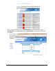
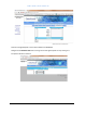
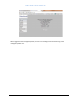
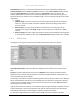
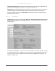
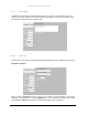
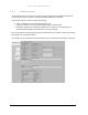
Table Of Contents
- 1 Introduction
- 2 DMR Operational Description
- 3 DMR Specifications
- 4 Installation guidelines
- 4.1 RF Exposure
- 4.2 Health and Safety
- 4.2 Health and Safety
- Read all available documentation and warnings before handling the equipment! Equipment failures due to improper handling are normally not covered by the product warranty!
- Keep passwords and other operational information away from unauthorized personnel!
- Bird Repeater system is an advanced technology system and should be handled by FCC Licensee or FCC approved staff.
- Read all documentation and warnings before handling the equipment.
- Obey all warning signs on the equipment and in documentation.
- The equipment may get hot during operation, do not operate outside permitted temperature range and keep away from heat sensitive material!
- The equipment contains ESD sensitive components. Open the equipment ONLY in a safe location designed for handling ESD products and use grounding devices! Opening the unit is not intended for field maintenance!
- The equipment contains ESD sensitive components. If not handled with care critical components may be damaged or destroyed. To avoid any damage due to ESD standard ESD precautions shall be used when handling the equipment.
- The product transmits RF signals keep away from Antennas and other radiating devices.
- Repeaters generate radio signals which are transmitted by the connected antennas. Installations should always be done so that the radiation exposure doesn’t exceed the recommendation set up by local authorities.
- Consult a FCC licensee or other applicable regulation body for details on RF requirements and safety issues on RF!
- Electrical installation shall be done in accordance with local safety regulations and laws.
- Make sure to use the equipment only in its intended applications and on the allowed frequencies.
- Avoid overheating by avoiding sunlight exposure!
- 4.2.1 Installing the DMR Repeater Unit
- 4.2.2 Antenna Connections
- 4.2.3 Power AC
- 5 DMR Repeater Commissioning

BIRD DMR USER MANUAL
16
Revision 2
Self-oscillation protection is a function for detection of eventual issues/problems related to the
Antenna isolation between Service and Donor Antenna´s. In case of low isolation between the two
antennas (Service & Donor) the repeater will begin to self-oscillate in the usual manner, but
however self-oscillation protection in this case will immediately intervene and lower the gain to a
safe level equal to the isolation minus the stability margin. There are separate settings for UL and DL
respectively;
• ON/OFF
• Stability margin. The value set of how much lower the gain should be than the calculated
isolation in case of issues with the isolation between the antennas. Range of this value is
from 0.0 – 20 dB.
• Recovery time. This is the time limit before the repeater tries to reset the gain to the
originally actual set gain in RF config. Range for the recovery time is between 30 – 86400
seconds.
• Recovery margin. Set value of gain level above the actual set gain (specified in RF config) that
is used when the repeater recovers after the Recovery time. Range is between 0.0 – 20.0 dB.
5.2.5 RF Status
Generally this menu gives a current status overview for both of the links in the repeater.
Start and stop frequency of both UL and DL are displayed in the firs field as seen in above screen
shot.
Set gain is gain value defined and set by the user. Max gain is the parameter that ALC and other
algorithms, such as the link symmetry feature and antenna oscillation detection, defines/sets is the
current maximum gain of the repeater.
For example, if the antenna oscillation detection algorithm detects antenna isolation issues, Max gain
will be automatically be reduced to a new calculated value. The operation is performed as Antenna
isolation minus set stability margin, which in that case is lower than the set gain. Gain field reflects
the actual gain value set by the user.
If by any chance antenna isolation is an issue while commissioning for example, the field for antenna
isolation will display a certain value measured in dB, and the alarm will be generated. Gain will be
automatically reduced with a certain margin in respect to the Antenna isolation.
For example, if displayed Antenna isolation value is >90dB, then there should be no problem.