
Operation Manual
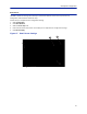
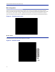
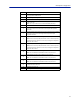
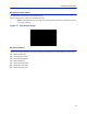
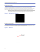
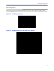
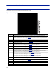
Table Of Contents
- Safety Precautions
- About This Manual
- Table of Contents
- Chapter 1 Introduction
- Chapter 2 System Description
- Chapter 3 Installation guidelines
- Chapter 4 DAS Software Configuration
- Chapter 5 Commissioning
- Chapter 6 RF Commissioning
- Chapter 7 Troubleshooting
- Alarms
- Base Station Gateway (BGW) Alarms
- Fiber Optic Remote (FOR) Alarms
- Remote Unit (RU) Alarms
- Fiber optic Interface (FOI) Alarms
- Base Station Interface (BIU) Alarms
- Medium Power Amplifier (PA) Alarms
- Variable Gain Amplifier (VGA) Alarms
- Analog Pre-distortion (APD) Amplifier Alarms
- Multi-carrier Power Amplifier Interface (MPI) alarms
- Alarms
- Chapter 8 Model Identification

Fiber Distributed Antenna System (Fiber DAS)
73
BIU RF1 Settings
This page will allow the user to change the attenuator values in the BIU for the path selected.
Figure 70 BIU RF1 Settings
1
2
3
Item Description
1
Attenuator setting for the downlink path. Enter a value from -14 to -44
(range varies depending of frequency band).
Note: Click Submit after entering value.
2
Attenuator/Gain setting for the uplink path.
Enter a value from -17 to 12 (range varies depending of frequency band).
Note that the BIU has raw gain in the uplink path on certain BIU types (gain
can be determined by positive value in the setting range.
A selection of 12 indicates full gain of 12dB in the BIU.
A selection of 9 will decrease the BIU uplink output by 3dB.
A selection of 0 will decrease the BIU uplink output by 12dB.
A selection of -17 will decrease the BIU uplink output by 29dB.
Note: Click Submit after entering value.
3
This selection turns the uplink path On or Off (maximum attenuation
setting).