
Operation Manual
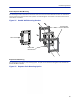
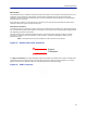
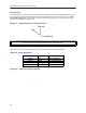

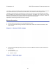
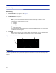
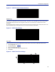
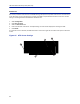
Table Of Contents
- Safety Precautions
- About This Manual
- Table of Contents
- Chapter 1 Introduction
- Chapter 2 System Description
- Chapter 3 Installation guidelines
- Chapter 4 DAS Software Configuration
- Chapter 5 Commissioning
- Chapter 6 RF Commissioning
- Chapter 7 Troubleshooting
- Alarms
- Base Station Gateway (BGW) Alarms
- Fiber Optic Remote (FOR) Alarms
- Remote Unit (RU) Alarms
- Fiber optic Interface (FOI) Alarms
- Base Station Interface (BIU) Alarms
- Medium Power Amplifier (PA) Alarms
- Variable Gain Amplifier (VGA) Alarms
- Analog Pre-distortion (APD) Amplifier Alarms
- Multi-carrier Power Amplifier Interface (MPI) alarms
- Alarms
- Chapter 8 Model Identification

Fiber Distributed Antenna System (Fiber DAS)
63
AC Power Input
The Bird repeater only comes with an AC input option. The voltage range will support 120VAC or 240VAC, 50 or 60
Hz. The remote ships with a weather proof C13 connector and weather proof strain relief housing. The unit does
not ship with a power cord - only the power connector. The installation contractor will need to provide a power
cable of at least 14AWG, 3 conductor cable.
Figure 57 Weatherproof AC Input Connector
Live
Neutral
Ground
WARNING
Electrical installation should only be performed by a licensed electrician.
External Alarm Connection
The external alarm port on the repeater requires an IP 67 D-sub connector (not supplied by Bird).
Table 69 Alarm Definitions
Alarm Input Level Alarm Text
1 (Pin 9)
Error Battery voltage low
2 (Pin 4)
Critical Loss of main AC power
3 (Pin 8)
Warning External alarm 3
4 (Pin 3)
Error External alarm 4
Figure 58 External Alarm Connector