
Operation Manual
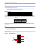
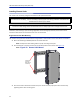
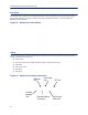
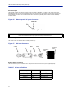
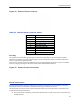
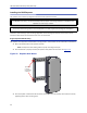
Table Of Contents
- Safety Precautions
- About This Manual
- Table of Contents
- Chapter 1 Introduction
- Chapter 2 System Description
- Chapter 3 Installation guidelines
- Chapter 4 DAS Software Configuration
- Chapter 5 Commissioning
- Chapter 6 RF Commissioning
- Chapter 7 Troubleshooting
- Alarms
- Base Station Gateway (BGW) Alarms
- Fiber Optic Remote (FOR) Alarms
- Remote Unit (RU) Alarms
- Fiber optic Interface (FOI) Alarms
- Base Station Interface (BIU) Alarms
- Medium Power Amplifier (PA) Alarms
- Variable Gain Amplifier (VGA) Alarms
- Analog Pre-distortion (APD) Amplifier Alarms
- Multi-carrier Power Amplifier Interface (MPI) alarms
- Alarms
- Chapter 8 Model Identification

Installation guidelines
58
Figure 48 External Alarm Connector
Table 68
Pin Function
1
Alarm relay output NC
2
Alarm relay output NO
3
Alarm input 4
4
Alarm input 2
5
Alarm input ground
6
Alarm relay output NC
7
Alarm relay output NO
8
Alarm input 3
9
Alarm input 1
External Alarm Connector Pinout
Grounding
The remotes are furnished with a ground lug to be used if chassis grounding is required to meet local code or
installation requirements. The external grounding lug must be used when the remote is installed in applications
where it is susceptible to lightening strikes.
If the remote is mounted in areas with high EMF such as near high amperage transformers, turbines or broadcast
antennas, properly grounding the chassis will provide reduce the likelihood interference.
Figure 49 Remote Ground Connection
Remote Unit Verification
Once the remote has been properly installed and all connections made the unit may be powered up. The unit is
automatically powered up once power is applied to the AC plug on the bottom of the unit.
The typical power cycle of the remote is approximately 90 seconds. The red and green LED on the bottom of the
remote will flash during the boot cycle.
Once the boot cycle is complete, a solid red LED indicates there is no fiber connection or communication to
the DAS head end.