
Operation Manual
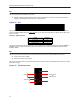
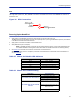
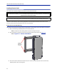
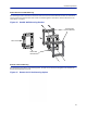
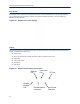
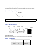
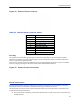
Table Of Contents
- Safety Precautions
- About This Manual
- Table of Contents
- Chapter 1 Introduction
- Chapter 2 System Description
- Chapter 3 Installation guidelines
- Chapter 4 DAS Software Configuration
- Chapter 5 Commissioning
- Chapter 6 RF Commissioning
- Chapter 7 Troubleshooting
- Alarms
- Base Station Gateway (BGW) Alarms
- Fiber Optic Remote (FOR) Alarms
- Remote Unit (RU) Alarms
- Fiber optic Interface (FOI) Alarms
- Base Station Interface (BIU) Alarms
- Medium Power Amplifier (PA) Alarms
- Variable Gain Amplifier (VGA) Alarms
- Analog Pre-distortion (APD) Amplifier Alarms
- Multi-carrier Power Amplifier Interface (MPI) alarms
- Alarms
- Chapter 8 Model Identification

Installation guidelines
52
RFU
The integrated repeater unit, RFU, DMR400 is mounted in the Master Unit chassis. The DMR400 uses two slots in
the Master Unit.
Figure 38
Rebroadcast
Uplink/
Downlink
RF
Source
Donor
Antenna
Service
Antenna
RFU Connections
Powering Up the Head End
1. Apply power to the BGW by pressing the power button on the left side of the unit.
The BGW requires approximately 5 minutes to completely boot up. During the BGW boot process, the modules
in the Master Unit will flash Red and Green.
2. Apply power to the Ethernet Switch and the Master Unit.
3. Verify BGW boot cycle is complete,
Note: The BGW will have green LED's lit even when powered off. This is part of the LAN wake up fea-
ture. When the BGW is running there will be three LED's lit and the hard drive icon showing activity.
4. See
Table 65
for the LED alarm codes for the modules in the Master Unit.
After the BGW boot process is complete, all modules in the Master Unit should have some LED indication. If
not, see
Table 66
.
Table 65 Master Unit Module LED Indicators
Status LED Indication
Normal Green - slow flash
Incoming Alarm Solid Red - Limited to 5 seconds
Warning Red LED flashes 1 Hz 1/8 duty cycle
Error Red LED flashes 2Hz ¼ duty cycle
Critical Red LED remains solid
Table 66 Master Unit Troubleshooting
Malfunction Corrective Action
If no modules have LED indications
Check Power cable to PSU.
Check power source for Master Unit.
Check connection from PSU to Chassis.
If a module does not have LED ON
Indicator
Verify the module is properly seated into
the chassis.
Move a module to another slot on the
Master Unit chassis.
Replace module.