
Operation Manual
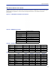
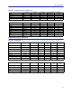
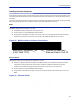
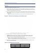
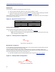
Table Of Contents
- Safety Precautions
- About This Manual
- Table of Contents
- Chapter 1 Introduction
- Chapter 2 System Description
- Chapter 3 Installation guidelines
- Chapter 4 DAS Software Configuration
- Chapter 5 Commissioning
- Chapter 6 RF Commissioning
- Chapter 7 Troubleshooting
- Alarms
- Base Station Gateway (BGW) Alarms
- Fiber Optic Remote (FOR) Alarms
- Remote Unit (RU) Alarms
- Fiber optic Interface (FOI) Alarms
- Base Station Interface (BIU) Alarms
- Medium Power Amplifier (PA) Alarms
- Variable Gain Amplifier (VGA) Alarms
- Analog Pre-distortion (APD) Amplifier Alarms
- Multi-carrier Power Amplifier Interface (MPI) alarms
- Alarms
- Chapter 8 Model Identification

Fiber Distributed Antenna System (Fiber DAS)
47
Master Unit
The Master Unit is designed to be installed in a 19" rack.
Before installing, consider cable routing for all cards to be installed in the Master Unit. The installer may
want to consider horizontal cable managers to be mounted above and below the Master Unit to aid in the
installation and ongoing maintenance of the system.
Each card in the Master Unit will require an Ethernet connection to the BGW in order to be programmed
and monitored. Install contractor provided Ethernet cable between the appropriate Ethernet port and the
Ethernet switch.
Note: The port number on the Master Unit is in reverse order on the back of the Master Unit.
Figure 30 Ethernet Port Numbering, Front and Rear Views
1
1
2
2
3
3
4
4
5
5
6
6
7
7
8
8
9
9
10
10
11
11
12
12
13
13
14
14
15
15
16
16
Only the active port on the Master Unit requires an Ethernet connection.
Example: The wide BIU uses two slots in the Master Unit. If installed in slots #1 and #2, only slot
#1 will make physical connection to the backplane. Install an Ethernet cable on the back of the
Master Unit in port #1 to provide the BIU with BGW connectivity.
Note: It is recommended Ethernet cables be installed on all ports. In the event of future configuration
changes this will ensure BGW connectivity regardless of slot changes.
All open slots on the Master Unit require a blank cover plate to allow for proper air circulation. Blank
plates must be ordered separately.
Table 62 Available Blank Cover Plates
Part Number Slots Covered
DBP101 1 Slot
DBP102 2 Slots
DBP104 4 Slots