
Operation Manual
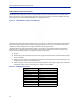
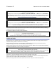
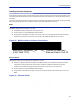
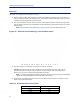
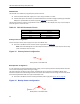
Table Of Contents
- Safety Precautions
- About This Manual
- Table of Contents
- Chapter 1 Introduction
- Chapter 2 System Description
- Chapter 3 Installation guidelines
- Chapter 4 DAS Software Configuration
- Chapter 5 Commissioning
- Chapter 6 RF Commissioning
- Chapter 7 Troubleshooting
- Alarms
- Base Station Gateway (BGW) Alarms
- Fiber Optic Remote (FOR) Alarms
- Remote Unit (RU) Alarms
- Fiber optic Interface (FOI) Alarms
- Base Station Interface (BIU) Alarms
- Medium Power Amplifier (PA) Alarms
- Variable Gain Amplifier (VGA) Alarms
- Analog Pre-distortion (APD) Amplifier Alarms
- Multi-carrier Power Amplifier Interface (MPI) alarms
- Alarms
- Chapter 8 Model Identification

Installation guidelines
46
Installing Headend Equipment
All equipment must be properly grounded. Ground peg in the main connector for both head-end gear (Master Unit)
and remote gear (Remote Units) must be connected to Phase, Neutral and Ground in a proper way before power is
connected.
The chassis of the remote and the rack of the master unit should be grounded to a potential bar or safety grounding
bar when operated. All electrical installations should be done by a certified electrician only.
BGW
The BGW is designed to be installed in a 19" rack.
The BGW is typically mounted near the top of the rack.
Connect power to an available NEMA5-15R receptacle.
Using installer provided Ethernet cable, connect the “Ext” port to the appropriate back-haul connection.
The back-haul connection can be DSL, off air modem, LAN, WAN. See BGW set up instructions.
Figure 28
Back-haul Connection
(LAN, WAN, ETC)
Connect to Head end
Ethernet Switch, Port 25
BGW Installation, Ethernet Connections
Ethernet Switch
The Ethernet switch, ETH, is designed to be installed in a 19" rack.
Placement is typically between the BGW and the Master Frame Unit. Placement consideration should
include proper routing of Ethernet cables and the installation of additional cables after the initial
installation is complete. Mounting may with Ethernet ports to the front or rear of the rack.
Connect power to an available NEMA5-15R receptacle.
Using installer provided Ethernet cable, connect port 25 of the Ethernet switch to the “INT” port on the
BGW.
Figure 29 Ethernet Switch