
Operation Manual
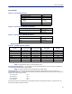
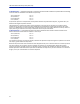
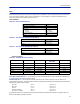
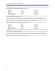
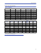
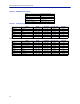
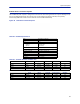
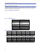
Table Of Contents
- Safety Precautions
- About This Manual
- Table of Contents
- Chapter 1 Introduction
- Chapter 2 System Description
- Chapter 3 Installation guidelines
- Chapter 4 DAS Software Configuration
- Chapter 5 Commissioning
- Chapter 6 RF Commissioning
- Chapter 7 Troubleshooting
- Alarms
- Base Station Gateway (BGW) Alarms
- Fiber Optic Remote (FOR) Alarms
- Remote Unit (RU) Alarms
- Fiber optic Interface (FOI) Alarms
- Base Station Interface (BIU) Alarms
- Medium Power Amplifier (PA) Alarms
- Variable Gain Amplifier (VGA) Alarms
- Analog Pre-distortion (APD) Amplifier Alarms
- Multi-carrier Power Amplifier Interface (MPI) alarms
- Alarms
- Chapter 8 Model Identification

System Description
30
FCC standards
Table 35 General Specifications
Noise Figure, Typical 3 dB
Delay excluding optical fiber < 0.5 μs
Instantaneous Band Width, Max 15 MHz
Power Supply
Standard
Optional
85 – 264 VAC
-32 to -100 VDC
Operating Temperature -25 to 55 °C (-13 to 131 °F)
Casing IP65
Table 36 Specifications DDH100 (Single Band)
Power Consumption, max, DDH100 210 W
Dimensions, W x D x H
11.8 x 5.1 x 27.6 in.
30 x 13 x 70 cm
Weight < 34 lbs (15.2 kg)
Table 37 Specifications DDH200 (Dual Band)
Power Consumption, max, DDS200 420 W
Dimensions, W x D x H
11.8 x 8.7 x 27.6 in.
30 x 22 x 70 cm
Weight < 60 lbs (27.2 kg)
Cellular Products
Table 38 Available Products, FCC/IC
System UL Frequency MHz DL Frequency MHz
Pout, DL,
dBm (RMS)
Standard
LTE LB 698 - 716 728 - 746 43 FCC/IC
LTE UB 776 – 787†
746 -757
†
† Sub-bands available
43 FCC/IC
iDEN 806 - 824 851 - 869 40 FCC/IC
Cellular 824 - 849 869 - 894 43 FCC/IC
PCS1900 1850 - 1915 1930 - 1995 43 FCC/IC
AWS 1710 - 1780 2110 - 2180 43 FCC/IC
2600 LTE 2500 - 2570 2620 - 2690 43 FCC/IC
Note: All specifications subject to change without notice.
Class B Industrial Booster — This equipment is a Class B Industrial Booster and is restricted to installation as
an In-building Distributed Antenna System (DAS).
Note: RF exposure distances are calculated using a 17 dBi antenna
FCC RF Exposure — This equipment complies with the FCC RF radiation exposure limits set forth for an
uncontrolled environment. This equipment should be installed and operated with the following minimum distances
between the radiator and your body:
2600 LTE (DDH 2600) 309 cm
AWS3 (DDHAWS3) 309 cm
PCS1900 (DDH1900) 309 cm
Cellular (DDH850) 406 cm
If system will operate on multiple bands, the separation distance required shall be equal to, or greater than, the
band with the largest separation distance.