
Operation Manual
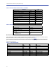
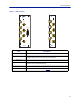
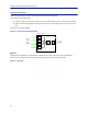
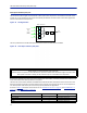
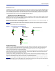
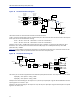
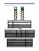

Table Of Contents
- Safety Precautions
- About This Manual
- Table of Contents
- Chapter 1 Introduction
- Chapter 2 System Description
- Chapter 3 Installation guidelines
- Chapter 4 DAS Software Configuration
- Chapter 5 Commissioning
- Chapter 6 RF Commissioning
- Chapter 7 Troubleshooting
- Alarms
- Base Station Gateway (BGW) Alarms
- Fiber Optic Remote (FOR) Alarms
- Remote Unit (RU) Alarms
- Fiber optic Interface (FOI) Alarms
- Base Station Interface (BIU) Alarms
- Medium Power Amplifier (PA) Alarms
- Variable Gain Amplifier (VGA) Alarms
- Analog Pre-distortion (APD) Amplifier Alarms
- Multi-carrier Power Amplifier Interface (MPI) alarms
- Alarms
- Chapter 8 Model Identification

System Description
16
DOI300 Series FOI
The DOI300 series supports a single fiber optic link. The fiber-optic interface can either be a WDM (DOI302) which is
most commonly used or an optional duplex feed with separate UL and DL fibers (DOI301). Bird also offers a WDM
option (DOI380x). The WDM utilizes the duplex feed style card but the wavelength for the downlink are defined by
the "x" in the DOI380x part number. Note that the Remote Unit will need to be ordered with the correct WDM
uplink wavelength. Refer to the chart for the WDM wavelengths offered.
DOI300 Series Serving Multiple Remotes
The DOI300 Series FOI can serve up to 4 Remote Units on a single fiber run when using an optical splitter in the first
Remote Unit. When utilizing the DOI302 WDM module each Remote Unit in the series must have different optical
wavelengths in the uplink path to avoid interference.
When utilizing optical splitters, the optical loss of the splitter mus
t be accounted for in the optical link budget. The
DOI300 series FOI has a maximum link budget of 15 dBo.
Figure 13
shows the allowed FOI to FOR/Remote configurations. Bird offers various splitter options for the FOR/
Remote to help account for optical losses. The standard optical splitter will have balanced outputs for each path.
Consult with Bird engineering for special applications.
Figure 13 FOI to Remote Unit Configurations
DeltaNode
Wireless Technology
TM
FOI
ALM
ON
UL OUT 1
OPTO IN/OUT
TP DL
RES
TP UL
DL IN 1
DL IN 2
UL OUT 2
DeltaNode
Wireless Technology
TM
FOI
ALM
ON
UL OUT 1
OPTO IN/OUT
TP DL
RES
TP UL
DL IN 1
DL IN 2
UL OUT 2
Point-to-Point
Daisy-Chained Remotes
Hybrid Split
DeltaNode
Wireless Technology
TM
FOI
ALM
ON
UL OUT 1
OPTO IN/OUT
TP DL
RES
TP UL
DL IN 1
DL IN 2
UL OUT 2
Point-to-Multipoint
DeltaNode
Wireless Technology
TM
FOI
ALM
ON
UL OUT 1
OPTO IN/OUT
TP DL
RES
TP UL
DL IN 1
DL IN 2
UL OUT 2
Functional description
The FOI has a nominal gain of 35 dB and the laser transmitter should see a maximum composite input power of
0 dBm. This means that for 0 dB attenuation in the downlink a maximum input of -35 dBm composite power is
recommended (when attenuators are set to 0 dBm). If the downlink attenuator is set to a higher value the
maximum recommended input is adjusted accordingly.
The output power of the laser is calibrated to 3000 μW. This can be used to check the loss over fiber in the remote
because the remote reports the received optical levels. The loss may be different in the uplink compared to the
downlink because of different wavelengths on the laser.
The FOI contains several adjustable attenuators which are used to compensate for loss before the FOI (e.g. in the
ICU) and for loss on the fiber in the uplink. There are two sets of RF ports on the FOI that can be used to connect
signals from two different strips in the rack-mount ICU, or two different MFU ICUs.
Figure 14
is a block diagram showing the downlink path in the FOI and how the test port is connected. There are
two attenuators that can be set in the downlink path. This allows for balancing the input signals from two different
signal sources so that they can share the dynamics of the laser properly.