
Operation Manual
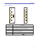
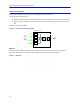
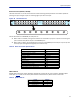
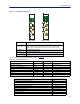

Table Of Contents
- Safety Precautions
- About This Manual
- Table of Contents
- Chapter 1 Introduction
- Chapter 2 System Description
- Chapter 3 Installation guidelines
- Chapter 4 DAS Software Configuration
- Chapter 5 Commissioning
- Chapter 6 RF Commissioning
- Chapter 7 Troubleshooting
- Alarms
- Base Station Gateway (BGW) Alarms
- Fiber Optic Remote (FOR) Alarms
- Remote Unit (RU) Alarms
- Fiber optic Interface (FOI) Alarms
- Base Station Interface (BIU) Alarms
- Medium Power Amplifier (PA) Alarms
- Variable Gain Amplifier (VGA) Alarms
- Analog Pre-distortion (APD) Amplifier Alarms
- Multi-carrier Power Amplifier Interface (MPI) alarms
- Alarms
- Chapter 8 Model Identification

System Description
12
Figure 7 BIU Interfaces
BIU
ALM
ON
DL/UL BTS 1
TP UL 1
EXTERNAL
ALARM
TP UL 2
DL OUT 1
UL IN 1
DL OUT 2
UL IN 2
DL/UL BTS 2
BIU
ALM
ON
DL/UL BTS 1
TP UL 1
TP UL 2
DL OUT 1
UL IN 1
DL OUT 2
UL IN 2
DL/UL BTS 2
Item Description
DL/UL BTS 1 / 2
Connection from the radio base station (RBS).
TP UL 1/2
Test port for the uplink of the DL/UL BTS port. The signal will be 3dB below
the DL/UL BTS port. Port is not valid on the simplex BIU.
DL OUT 1/2
Simplex downlink feed to the FOI.
UL IN 1/2
Simplex uplink from the FOI. The BIU will attenuate and/or amplify the signal
and then route to the DL/UL BTS port.
EXTERNAL ALARMS
Used for external alarm monitoring (DBI3xx, two slot version only).
ON/ALM LED
The LEDs indicate various states, see
Table 7
.