
Operation Manual
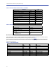
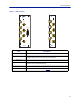
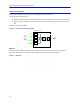
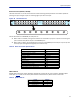
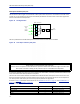
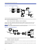
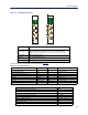

Table Of Contents
- Safety Precautions
- About This Manual
- Table of Contents
- Chapter 1 Introduction
- Chapter 2 System Description
- Chapter 3 Installation guidelines
- Chapter 4 DAS Software Configuration
- Chapter 5 Commissioning
- Chapter 6 RF Commissioning
- Chapter 7 Troubleshooting
- Alarms
- Base Station Gateway (BGW) Alarms
- Fiber Optic Remote (FOR) Alarms
- Remote Unit (RU) Alarms
- Fiber optic Interface (FOI) Alarms
- Base Station Interface (BIU) Alarms
- Medium Power Amplifier (PA) Alarms
- Variable Gain Amplifier (VGA) Alarms
- Analog Pre-distortion (APD) Amplifier Alarms
- Multi-carrier Power Amplifier Interface (MPI) alarms
- Alarms
- Chapter 8 Model Identification

Fiber Distributed Antenna System (Fiber DAS)
11
Table 5 RF and Electrical Performance of the BIU
Parameter Value
Downlink attenuation Settable 10-30 ± 3 dB
Uplink Gain for modules < 1000 MHz Settable 10 to 20 ± 3 dB
Uplink Gain for modules > 1000 MHz Settable -10 to 10 ± 3 dB
IM3 performance > 55 dB
Max input non-destructive < 36 dBm
High input alarm threshold level >33 dBm
Low input alarm threshold level <13 dBm
Input return loss > 20 dB
Impedance for all RF ports 50 Ω
Isolation between ports > 60 dB
Power consumption < 15 W
Temperature range 0-45 °C (32 to 113 °F)
Table 6 BIU Mechanical Specifications
Parameter Value
Base station RF ports SMA, Female
Test ports uplink (if present) SMA, Female
Interconnecting RF ports to ICU QMA, Female
Alarm connector (optional) DB9, Female
Module Width
DBI3xx
DBI3xxC(compact)
2 Slots
1 slot
BIU Indicator Operation
There are two LEDs located on the BIU front panel. One is the power LED (green), the other is the alarm LED (red).
Both LEDs indicate a number of states by different flashing sequences, see
Table 7
.
In an error state the web interface should be used to check the actual condition of the BIU but the LEDs can give a
quick indication on the state of the unit. The LEDs are also useful for locating the physical unit if several BIUs are
installed in the same rack.
Table 7
State ON LED ALM LED Note
Booting 2 Hz Off Normal boot
Booting standalone mode 2 Hz 2 Hz Not attached to rack
Booting read of MAC address failed 2 Hz On Error
Starting 0,1 Hz 90% 0,1 Hz 90% Kernel startup
Operation 0,5 Hz 10% Off Normal operation
Operation 0,5 Hz 10% 1 Hz 10% Minor alarm state
Operation 0,5 Hz 10% 2 Hz 25% Major alarm state
Operation 0,5 Hz 10% On Critical alarm state
Indicator Behavior