
Operation Manual
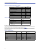
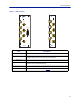
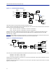
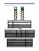

Table Of Contents
- Safety Precautions
- About This Manual
- Table of Contents
- Chapter 1 Introduction
- Chapter 2 System Description
- Chapter 3 Installation guidelines
- Chapter 4 DAS Software Configuration
- Chapter 5 Commissioning
- Chapter 6 RF Commissioning
- Chapter 7 Troubleshooting
- Alarms
- Base Station Gateway (BGW) Alarms
- Fiber Optic Remote (FOR) Alarms
- Remote Unit (RU) Alarms
- Fiber optic Interface (FOI) Alarms
- Base Station Interface (BIU) Alarms
- Medium Power Amplifier (PA) Alarms
- Variable Gain Amplifier (VGA) Alarms
- Analog Pre-distortion (APD) Amplifier Alarms
- Multi-carrier Power Amplifier Interface (MPI) alarms
- Alarms
- Chapter 8 Model Identification

System Description
10
The schematic in
Figure 6
shows one of the channels in the BIU. The signal detector for the downlink level alarms is
shown in the top right corner.
The UL1 and UL2 uplink test ports are 3 dB lower than the signal on the corresponding DL/UL BTS port.
Figure 6 Schematic of One BIU RF Path
Table 4
lists standard cellular BIU’s. Other configurations are available upon request as well as units without
internal duplex filtering.
Table 4 Standard Variants of the BIU
Configuration UL MHz DL MHz RF Input High Level P/N Low Level P/N
2 x FM - 87-108 Simplex DBI302 DBI402
2 x VHF 136-174 136-174 Simplex DBI313 DBI413
2 x TETRA 390 MHz
†
† There are several options for the TETRA 5 MHz standard bands.
380-385 390-395 Duplex DBI301 DBI401
2 x UHF 450-470 450-470 Duplex DBI314 DBI414
2 x 700 MHZ ABC-band 698-716 728-746 Duplex DBI307 DBI407
2 x 700 Upper C 777-787 746-756 Duplex DBI304 DBI404
2 x 700 Public Safety 799-805 769-775 Duplex DBI306 DBI406
2 x SMR 800 806-824 851-869 Duplex DBI303 DBI403
2 x 850 MHz 824-849 869-894 Duplex DBI308 DBI408
2 x 800 832-862 791-821 Duplex DBI305 DBI405
2 x GSM-R 900 876-880 921-925 Duplex DBI310 -
2 x 900 MHz 880-915 925-960 Duplex DBI309 DBI409
2 x 1800 MHz 1710-1785 1805-1880 Duplex DBI318 DBI418
2 x 1900 MHz 1850-1915 1930-1995 Duplex DBI319 DBI419
2 x UMTS 2100 MHz 1920-1980 2110-2170 Duplex DBI320 DBI420
2 x AWS 2100 MHz 1710-1780 2110-2180 Duplex DBI321 DBI421
2 x LTE 2600 2500-2570 2620-2690 Duplex DBI326 DBI426