
Operation Manual
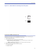
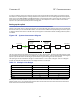
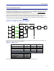
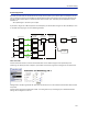
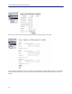
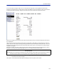
Table Of Contents
- Safety Precautions
- About This Manual
- Table of Contents
- Chapter 1 Introduction
- Chapter 2 System Description
- Chapter 3 Installation guidelines
- Chapter 4 DAS Software Configuration
- Chapter 5 Commissioning
- Chapter 6 RF Commissioning
- Chapter 7 Troubleshooting
- Alarms
- Base Station Gateway (BGW) Alarms
- Fiber Optic Remote (FOR) Alarms
- Remote Unit (RU) Alarms
- Fiber optic Interface (FOI) Alarms
- Base Station Interface (BIU) Alarms
- Medium Power Amplifier (PA) Alarms
- Variable Gain Amplifier (VGA) Alarms
- Analog Pre-distortion (APD) Amplifier Alarms
- Multi-carrier Power Amplifier Interface (MPI) alarms
- Alarms
- Chapter 8 Model Identification

RF Commissioning
116
Practical approach
Now that we know what we should have we can easily set the system up. You need a spectrum analyzer to do this
and it is easiest to connect it into the BIU port. Remember that when you measure here, the signal should also go
through the BTS coupler before it reaches the base station receiver port. Therefore you should expect to read a
value that is:
Your expected gain + the loss in your coupler.
If you want a net gain of -5 dB and you have a 15 dB coupler, you should read a net gain of +10 on the BIU port. This
is now what we are going to use in the following example.
!
"#
Turn on the RF
Connect to the BIU and turn on the RF. Set the attenuator in the medium range for the uplink that you are
measuring. This allows you later to adjust it up and down as necessary to get the correct gain for the uplink chain.
Setting them to 10 dB is a good idea. DL supervision can be left as is for now and also DL attenuation which we will
set up later.
Connect to the FOI card and select Opto and RF – RF Config and set it up according to your Fiber-DAS calculator
settings. Do not forget to turn RF on.