
Operation Manual
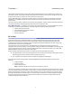
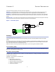
Table Of Contents
- Safety Precautions
- About This Manual
- Table of Contents
- Chapter 1 Introduction
- Chapter 2 System Description
- Chapter 3 Installation guidelines
- Chapter 4 DAS Software Configuration
- Chapter 5 Commissioning
- Chapter 6 RF Commissioning
- Chapter 7 Troubleshooting
- Alarms
- Base Station Gateway (BGW) Alarms
- Fiber Optic Remote (FOR) Alarms
- Remote Unit (RU) Alarms
- Fiber optic Interface (FOI) Alarms
- Base Station Interface (BIU) Alarms
- Medium Power Amplifier (PA) Alarms
- Variable Gain Amplifier (VGA) Alarms
- Analog Pre-distortion (APD) Amplifier Alarms
- Multi-carrier Power Amplifier Interface (MPI) alarms
- Alarms
- Chapter 8 Model Identification

1
Chapter 1 Introduction
The Bird fiber distributed antenna system (Fiber-DAS) was developed from the start with fiber-optic cable as the
distribution medium. This allows for excellent radio performance and best in class system noise figure of less than
3 dB, from the remote unit antenna port to the base station interface port.
The Bird Fiber-DAS system is a flexible and scalable solution, meaning the s
ystem can be tailored for almost any
requirement. This flexibility provides the user the ability to adjust many of the system’s parameters to fit their
specific needs.
This manual contains design, installation, and commissioning guidelines,
as well as system maintenance practices. It
also contains information regarding general practices within in the industry as well.
Fiber-DAS calculator — In addition to this manual, the Fiber-DAS calculator is an indispensable t
ool, this Excel
spreadsheet includes the following features, providing insight to how well the system will perform:
System Noise Figure calculator
Intermodulation performance calculator
Uplink / Downlink Balance
Dynamic headroom
RF on fiber
A fiber distributed antenna system (Fiber-DAS) is an efficient method of transmitting radio signals over large
distances. Our Fiber-DAS can provide as much as 30 km of fiber between the head-end and the remote unit,
providing that the radio access technology used in the Radio Access Network (RAN) does not suffer timing issues
and that the fiber loss is within the specification.
The Fiber-DAS uses an infra-red light source, modulated with the combined radio signals that need to be
propagated. The fiber channel system is ultra wide-band, ranging from 88 MHz up to 2600 MHz, thus covering most
types of radio communication systems including as FM broadcast, VHF communication radios, LTE, TETRA, GSM,
CDMA, WCDMA and many other radio access technologies.
Most land mobile radio and cellular systems use Frequency Division Duplex (FDD) which means:
Two separate fibers, one for the uplink (signals from the terminal towards the base station) and one for the
downlink (signals from the radio base station towards the terminal)
Or a single fiber and the signals must be multiplexed using different wavelengths.
Bird’s Fiber-DAS uses wave-length division multiplexing (WDM) as the standard configuration featuring the
following:.
Single mode fiber
Angled connectors
Up to 15 dB optical loss
Note: Separate UL/DL fibers can be used if it is necessary or desired.
The dynamic of the fiber is good enough to tolerate multi-carrier, multi-band and multi-operator solutions, but they
share the available dynamics and if there is a large number of carriers the fiber attenuation needs to be considered.
Because the modulation is analog the system requires the fibers to be of single mode type. All connectors used in
Bird’s Fiber-DAS equipment are SC-APC type. It is important that all connectors (i.e. patches) between the Master
Unit (MU) and the Remote Units (RU) be angled, otherwise reflections could result causing problems with the
quality of the signals through the system.