
User Manual
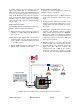
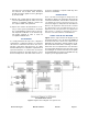
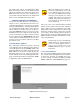
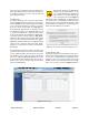
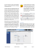
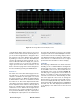
Table Of Contents
- Overview
- Unpacking
- Installation
- RF Exposure
- Exposition RF
- Signal Flow Block Diagram
- System Setup
- Operation
- Communicating with the Booster
- Maintenance and Repair
- Ethernet CONNECTIVITY
- Table of Contents

Bird Technologies Manual 7-9558-2.3 05/14/15 Page 20
on the Estimate button at the bottom of the screen
and the software will calculate the Delay time for
you. Press the Design button to design the filter.
The rejection scale of the display can be changed
by making a selection from the “maximum plot
rejection” drop down list. Choices include -10, -50,
and -100 dB scale. When the display is to your sat-
isfaction and does not violate any parameter
ranges press the Save and Close button to exit
back to the filters page then load the design into
the selected filter by pressing the Submit button.
Status Area
The status area of the Filter Detail page uses sta-
tus indicators to let the user know whether the
channel is enabled, if the test signal is on, and if
the carrier squelch is on. When the status indicator
is illuminated the feature is on and when it is dark
the feature is off. The Carrier Squelch status indi-
cator will be green if the channel is squelched. The
Carrier Squelch status indicator will stay dark if
there is no squelching even if the Carrier Squelch
radio button is set to enabled. A test signal can be
generated for any channel within the system or
every channel simultaneously. The output power
box displays the output power for the channel mod-
ule. This value should be close but not necessarily
exactly the same as the “Desired Output Level” dis-
cussed earlier. The box showing output power is
only displayed if the filter is giving an output power.
If the filter is not enabled or there is no signal
present then there would be no value to display.
LINK TAB
The link page is divided into four functional areas
including a row of command buttons running down
the left side of the screen, a link and settings area
in the middle of the screen, and a status area on
the right side of the screen as shown in Figure 15.
The link page is designed to interact with one
branch of a module at a time. The branch that is
selected for interaction is determined by the Link
box on the upper left of the screen. To change the
branch that you are going to interact with click on
the arrow to display the full drop down box. Scroll
down the list until the desired branch is highlighted
and click on it. The data displayed in the link area
of the display screen will now be for the selected
branch.
Figure 14: The design filter interactive display screen.