
User Manual
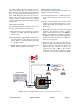
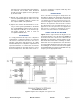
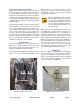
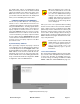
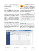
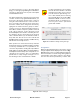
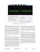
Table Of Contents
- Overview
- Unpacking
- Installation
- RF Exposure
- Exposition RF
- Signal Flow Block Diagram
- System Setup
- Operation
- Communicating with the Booster
- Maintenance and Repair
- Ethernet CONNECTIVITY
- Table of Contents

Bird Technologies Manual 7-9558-2.3 05/14/15 Page 17
the alarm status. This is accomplished by using
EOL (end-of-line) resistors at the alarm terminal
strip in the signal booster cabinet. The value of the
EOL resistors is a function of the alarm panel so
you should consult the manual for the alarm panel
when you are determining the resistor value.
COMMUNICATING WITH THE BOOSTER
The booster provides Ethernet connectivity that
allows access to a web-based user interface for
communicating with the control board, program-
ming the individual filters, checking system status,
etc. Communications will require connecting your
laptop computer to the Enet connector on the con-
trol board. Figure 8 shows the connector. A stan-
dard Ethernet crossover cable is used to make the
connection between your laptop computer and the
booster cabinet. Refer to Appendix A at the back
of this manual for detailed instructions on how to
properly connect your laptop computer to the Enet
port of the booster.
System Summary Submenu
Once your laptop computer is properly connected
to the signal booster the web-based user interface
screen will appear as shown in Figure 9 This is the
System Summary page which shows the IP and
MAC address of the control module. On the left-
hand side of the screen are a list of the major sub-
menus available to the user including System Sum-
mary, Control Panel, Network Configuration, SNMP
Configuration, and User Administration.
When the webpage first comes up,
the Control Panel menu choice will
not be displayed. The user needs to
go to the User Administration Page
and type in the default user name
(admin) and default user password
(admin). After this login function is
performed the Control Page menu
choice will appear.
Place your cursor over a particular menu heading
and left click to make a selection. Each submenu
page contains a group of related functions. With
password protection enabled the user will only be
allowed to view the pages, however the user will
not be able to make changes without entering a
password. After entering a valid password via the
Admin submenu the pages will switch from read-
only to fully interactive.
Password protection is disabled by
default when your system leaves the
factory. To enable password protec-
tion for your system refer to the
ADMIN submenu page for specific
instructions.
Control Panel Submenu
The Control Panel submenu gives the user the abil-
ity to interface with and adjust the RF parameters
of the booster. Five tabs are available on the Con-
trol Panel Page including FILTERS, FILTER
DETAIL, LINK, FFT, and SYSTEM. Each page con-
NOTE
NOTE
Figure 9: System Summary page.