
User's Manual
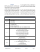
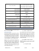
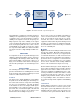
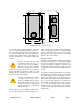
Table Of Contents
Table of Contents Manual 7-9485-1.7 09/12/11
Table of Contents
Overview............................................................................................................... 1
Down / Up Conversion......................................................................................... 2
Unpacking ............................................................................................................ 3
Installation............................................................................................................ 3
Location ............................................................................................................. 3
Mounting............................................................................................................. 3
Connections........................................................................................................ 3
Antenna Isolation ............................................................................................... 4
Required Equipment ......................................................................................... 5
Measurement Procedure .................................................................................. 5
RF Exposure (Exposition RF) ............................................................................ 6
Signal Flow Block Diagram ............................................................................... 6
Uplink and Downlink Input Signals ...................................................................... 6
Channel Module .................................................................................................. 8
Uplink and Downlink Output Signals ................................................................... 9
Operation.............................................................................................................. 9
Subassembly LED’s ........................................................................................... 9
Configuring the Channel Module ........................................................................ 9
Filters Tab ......................................................................................................... 11
Command Buttons .......................................................................................... 11
Filter Area ....................................................................................................... 12
Status Area ..................................................................................................... 12
Link Tab ............................................................................................................ 12
Command Buttons .......................................................................................... 12
Link and Settings Area.................................................................................... 13
Status Area ..................................................................................................... 13
Admin Tab......................................................................................................... 13
System Tab ....................................................................................................... 13
Figures and Tables
Figure 1: The Down / Up Converter Process ....................................................... 3
Figure 2: Cabinet Mounting ................................................................................. 4
Figure 3: Measuring Antenna Isolation................................................................. 5
Figure 4: Signal Flow Block Diagram ................................................................... 6
Figure 5: Booster Cabinet Front View .................................................................. 7
Figure 6: Enet Connector ..................................................................................... 9
Figure 7: Enter Your Password ............................................................................ 9
Figure 8: Web-Page Interface Filters Tab ........................................................... 10
Figure 9: Design Filter Interactive Display .......................................................... 10
Figure 10: Web-Page Interface Link Tab ............................................................ 11
Figure 11: Web-Page Interface Admin Tab......................................................... 12
Figure 12: Web-Page Interface System Tab ....................................................... 13
Table 1: Model number nomenclature................................................................... 1
Table 2: Specifications .......................................................................................... 2
Table 3: Subassembly LED Descriptions .............................................................. 8