
User's Manual
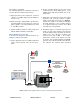
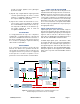
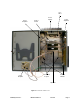
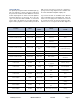
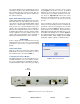
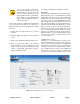
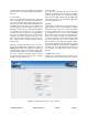
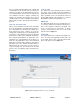
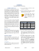
Table Of Contents

TX RX Systems Inc. Manual 7-9485-1.7 09/12/11 Page 9
up converter boards are used. Signal booster mod-
els that have the fiber-optic option installed in them
have enhanced down-converter boards that are
capable of dealing with the low level signals from
the optical conversion.
Uplink and Downlink Output Signals
Uplink and Downlink output signals leave the chan-
nel module at the UL OUT and DL OUT connectors
respectively. The 700 and 800 MHz uplink output
signals are combined with a directional coupler
then passed on to a power amplifier stage. The
output of the power amplifier is passed through a
triplexer then radiated from the donor antenna.
Downlink output signals leave the channel module
and are applied to a power amplifier stage. The
output of the power amplifier is passed through a
triplexer then radiated from the service antenna.
OPERATION
Power is applied to the channelized booster by
plugging in the AC or DC power cord (depending
on how th e system was configu red for input
power).
Subassembly LED’s
LED’s are located on several of the subassemblies
within the Booster cabinet. The function of each of
these indicator LED’s are listed in Table 3.
Configuring the Channel Module
The digital signal booster provides Ethernet con-
nectivity that allows access to a web-based inter-
face for programming the individual channels.
Programming will require connecting your laptop
computer to the Enet connector on the control
board. Figure 6 shows the connector. A standard
Ethernet crossover cable is used to make the con-
nection between your laptop and the booster cabi-
net. Refer to Appendix A at the back of this
manual for detailed instructions on how to properly
connect your computer to the Enet port of the
booster.
Once your laptop is properly connected to the sig-
nal booster, if password protection is enabled, the
password request box will appear in your web
browser as shown in Figure 7. Type in your pass-
word and press the OK button. The password box
will disappear and the web-based interface screen,
at the filters tab, will appear as shown in Figure 8.
The web based interface is divided into four pages
including FILTERS, LINK, ADMIN, and SYSTEM.
Each page contains a group of related functions.
Figure 7: Enter your password.
Figure 6: Enet connector on the control board.
Enet
Connector