
User's Manual
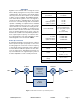
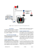
Table Of Contents
TX RX Systems Inc. Manual 7-9469-1.7 02/08/10 Page 3
Connections
All RF cabling connections to the booster should
be made and checked for correctness prior to pow-
ering up the system. Connectors are available from
the filter assemblies for connection to the signal
distribution system. Make sure the correct branch
of the distribution system is connected to its corre-
sponding uplink/downlink connector or the system
will not work properly. Using high quality connec-
tors with gold center pins is advised. Flexible
jumper cables made of high quality coax are also
acceptable for connecting to rigid cable sections.
The booster is designed to be plugged into a single
phase AC line (90 - 250 VAC at 50/60 Hz) or a + 28
Volt DC source. A connector will be available at the
back panel of the module cabinet for connecting
either the AC or DC source voltage. At the time of
manufacture the equipment will be configured for
either AC or DC operation as per the customers
request and only one of the connectors, AC or DC,
will be available on the back panel. Additionally,
the AC connector has a 5 Amp fuse for protection.
Antenna Isolation
Antenna isolation between uplink and downlink
should be measured before connecting the signal
booster to the antenna system. This step is neces-
sary to insure that no conditions exist that could
possibly damage the signal booster and should not
be skipped for even the most thoroughly designed
system.
Just like the feedback squeal that can occur when
the microphone and speaker get too close together
in a public address system, a signal booster can
start to self oscillate. This can occur when the iso-
lation between the Uplink and Downlink antennas
does not exceed the signal boosters gain by at
least 15 dB. Oscillation will reduce the effective-
ness of the system and may possibly damage
amplifier stages. Isolation values are relatively
easy to measure with a spectrum analyzer and sig-
nal generator.
REQUIRED EQUIPMENT
The following equipment is required in order to per-
form the antenna isolation measurements.
1) Signal generator for the frequencies of interest
capable of a 0 dBm output level. Modulation is
not necessary.
2) Bird Technologies “Signal Hawk” spectrum ana-
lyzer which will cover the frequencies of interest
and is capable of observing signal levels down
to -100 dBm or better.
3) Double shielded coaxial test cables made from
RG142, RG55 or RG223 coaxial cable.
MEASUREMENT PROCEDURE
To measure the antenna isolation perform the fol-
lowing in a step-by-step fashion.
1) Set the signal generator for a 0 dBm output level
at the center frequency of the boosters pass-
band.
2) Set the spectrum analyzer for the same center
frequency and a sweep width equal to or just
slightly greater than the passband chosen ear-
lier in step 1.
3) Temporarily connect the test leads of the signal
generator and spectrum analyzer together
using a female barrel connector, see Figure 2.
Observe the signal on the analyzer and adjust
the input attenuator of the spectrum analyzer
for a signal level that just reaches the 0 dBm
level at the top of the graticule.
4) Referring to Figure 2, connect the generator
test lead to one side of the antenna system and
the spectrum analyzer to the other then observe
the signal level. The difference between the
observed level and 0 dBm is the isolation
between the sections. If the signal is too weak
to observe, the spectrum analyzer’s bandwidth
may have to be narrowed and it’s input attenua-
tion reduced. The isolation value measured
should exceed the signal booster’s gain figure
by at least 15 dB.
5) Repeat step 4 again with the signal generator
set at the passband edges in order to see if the
isolation is remaining relatively constant over
the complete width of the passband.
6) Repeat the isolation measurements if necessary
at other system passbands to determine the
overall minimum isolation value for the system.
Physical modification of the antenna system
maybe required in order to reach an acceptable
minimum value.