
User's Manual
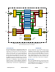
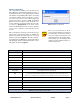
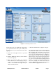
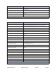
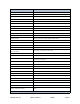
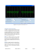
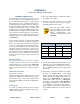
Table Of Contents

TX RX Systems Inc. Manual 7-9469-1.7 02/08/10 Page 9
COMMAND BUTTONS
Clicking on a command button (located on the
extreme left hand side of the screen) performs the
associated task immediately. The submit and
reload buttons in the bottom left corner allow any
changes you make to the display/interface boxes
to be downloaded to the booster. The submit and
reload buttons act like a trigger sending any
changes you made on the web-page interface
screen to the selected booster module, but only
after the button is pressed.
MESSAGE BARS
There are two message bars at the bottom of the
web-page screen. The rightmost message bar dis-
plays connection status messages and the leftmost
message bar displays system status messages.
The connection status messages reveal the rela-
tionship between the LAN interface and the control
board within the booster cabinet. Without a prop-
erly functioning connection you will not be able to
interface with the control board or individual mod-
ules. All of the possible connection status mes-
sages are listed in Table 3 along with a brief
description of what each message means. The
system status messages vary depending on what
aspect of the booster system you are interacting
with. All of the possible system status messages
are listed in Table 4.
DISPLAY/INTERFACE AREAS
The display/interface area of the web-based inter-
face is divided into five functional areas including;
Settings - this is a user interactive area where the
field engineer can program the operating charac-
teristics of the selected module. Each parameter in
the settings area can be changed by clicking in the
box and typing in the new values or by pointing at
an arrow to display a drop down box. Most of the
adjustable parameters have adjustment limitations
which can be displayed in a message box by click-
ing on the question mark symbol next to the
parameter. The parameters are self-explanatory.
Remember the changes you make are only appli-
cable to the selected channel module. After you
have made changes to the various parameters
press the “submit” command interface button
(lower left corner of the screen) in order to copy the
changes into the module itself.
Filters - this area allows you to modify the charac-
teristics of the digital filtering used by the channel
module. Parameters that can be changed include
the occupied bandwidth, adjacent channel offset,
passband ripple, adjacent channel rejection, and
delay.
When the “Design Filter” button is pressed a cus-
tom design template will be displayed as shown in
Figure 8. Remember the changes you make are
only applicable to the selected channel module.
After you have made changes to the various
parameters press the “submit” command interface
button (lower left corner of the screen) in order to
copy the changes into the module itself.
Information - this area is non-interactive and is
used to display basic information about the
selected channel module.
Data - this area is also non-interactive and displays
detailed technical parameters. The polling function
can be changed between either enabled or dis-
abled. Click on the bubble next to the function to
change the polling status. In the example shown in
figure 6 the polling is currently disabled. To enable
polling you would point at the bubble next to the
enable label and right click.
Status - this area is used to give a quick overview
of eight channel module parameters. Each param-
eter can be in one of three states; alert, active or
inactive. Each state is color coded as shown in fig-
ure 6.
Figure 7: Selecting a module.