
User's Manual
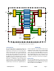
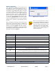
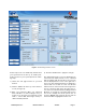
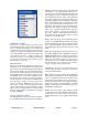
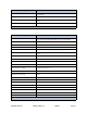
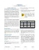
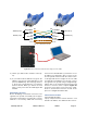
Table Of Contents

TX RX Systems Inc. Manual 7-9469-1.7 02/08/10 Page 7
Module Configuration
The channelized signal booster provides front
panel Ethernet connectivity that allows access to a
web-based interface for programming the individ-
ual modules. Programming will require connecting
your laptop computer to the User Interface connec-
tor on the front of the booster cabinet. Figure 4A
shows the interface connector (LAN). A standard
Ethernet crossover cable is used to make the con-
nection between your laptop and the booster cabi-
net. Refer to Appendix A at the back of this
manual for detailed instructions on how to properly
connect your computer to the LAN port of the
booster.
Once your laptop is properly connected to the sig-
nal booster, if password protection is enabled, the
password request box will appear in your web
browser as shown in Figure 5. Type in your pass-
word and press the OK button. The password box
will disappear and the web-based interface screen
will appear as shown in Figure 6.
Once your password has been
entered and validated a 15 minute
inactivity timer is started. If the user
does not make any changes to the
web page interface the system will re-
arm security once the inactivity timer
expires. The user will then need to re-
enter the password.
NOTE
Status LED
Green (flashing fast) Unit Identification (for several seconds only on command from User Interface)
Orange (slow flash) Unprogrammed unit (no settings set)
Off Unit disabled (no output from module)
Red (slow flash) External reference selected but is absent or not locked
Red (solid ON) Alarm of some kind (current or temp out of limits, LO not locked, filter not set)
Green (solid ON) all is OK
Channel Keyed
Slow Flash Unprogrammed unit (no settings set)
ON
Unit will transmit signal
if CTCSS and DCS disabled then signal present on input above carrier squelch threshold
Else if one is enabled then it means that the selected CTCSS or DCS code has been detected
OFF Unit will not transmit signal
Carrier Detect
Slow Flash Unprogrammed Unit (no settings set)
ON Signal present on input above carrier squelch threshold
OFF No signal present on input above carrier squelch threshold
Table 2: Channel Module Indicator LED’s
Figure 5: Enter your password.