
User's Manual
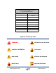
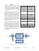
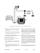
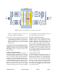
Table Of Contents
Table of Contents Manual 7-9469-1.1 06/10/09
Table of Contents
Overview............................................................................................................... 1
Down / Up Conversion......................................................................................... 2
Unpacking ............................................................................................................ 2
Installation............................................................................................................ 2
Location ............................................................................................................. 2
Antenna Isolation ............................................................................................... 2
Required Equipment ......................................................................................... 2
Measurement Procedure .................................................................................. 3
Functional Block Diagram Description ............................................................. 4
Downlink / Uplink Input Signals ........................................................................... 4
Downlink / Uplink Output Signals ........................................................................ 4
Channel Module 3-22322 .................................................................................... 4
Operation.............................................................................................................. 6
Module LED’s ..................................................................................................... 6
RF Exposure ........................................................................................................ 6
Figures and Tables
Figure 1: The Down / Up Converter Process ....................................................... 1
Figure 2: Measuring Antenna Isolation................................................................. 3
Figure 3: Functional Block Diagram ..................................................................... 4
Figure 4A: Module housing Front View ................................................................ 5
Figure 4B: Module Housing rear View.................................................................. 5
Figure 5: Channel Module Block Diagram............................................................ 6
Table 1: Specifications .......................................................................................... 1
Table 2: Channel Module Indicator LED’s............................................................. 7