
User's Manual
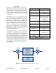
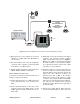
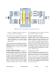
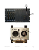
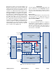

Table Of Contents

TX RX Systems Inc. Manual 7-9469-1.1 06/10/09 Page 6
Each branch consists of four boards; Digital, Local
Oscillator, Down Converter, and Up Converter. RF
signals enter the branch at the down converter
board where they are filtered, amplified, and con-
verted into a 70 MHz intermediate frequency. The
digital board digitizes the IF signal with an ADC.
The digitized samples are applied to a programma-
ble gated array for digital filtering. The filtered sig-
nals from the array are converted back into analog
by a DAC and output to the up converter board.
The up converter board converts the IF back into
the original UHF signal and outputs it from the
module. The Local Oscillator board generates the
reference signals for mixing and sampling. The
mixing frequency can range from 380 to 400 MHz
and is determined by the user via interface with the
micro controller on the digital board.
OPERATION
Power is applied to the unit by plugging in the AC
power cord. There is a Power-ON LED located on
the front of the unit (near the computer interface
connector) which will illuminate when power is
applied.
Module LED’s
There are six LED indicators on the front of each
channel module, 3 for the uplink branch and 3 for
the downlink branch. The function of indicator
LED’s are listed in Table 2.
RF EXPOSURE
To comply with FCC RF exposure compliance
requirements, a separation distance of at least 100
cm must be maintained between the antenna of
this device and all persons. This device must not
be co-located or operating in conjunction with any
other antenna or transmitter.
10M Ref
Alarm
Logic
Form 'C'
Squelch
RF Out (DL)
RF In (UL)
Out
10 MHz
+28 VDC
I2C
Form
"C"
Contacts
In
RF Out (UL)
RF In (DL)
LED
Connect
(UL)
LED
Connect
(DL)
LEDs
(3)
5.5V
5.5V
5.5V
DAC Out
(2)
LO
LO
Attn Cnl
(4)
ADC
in (2)
Vocm AGC
Cnl (2)
Freq Cnl
(3)
56M (3)
Up Converter Board
3-22302
Interface
Board
3-22315
LED
Board
3-22295
Down Converter Board
3-22308
LO Board
3-22312
Digital Board
3-22310
10M
28V
I2C
Thru Wall Cable
Figure 5: Channel Module block diagram.