
User's Manual
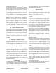
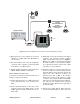
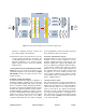
Table Of Contents

TX RX Systems Inc. Manual 7-9469-1.1 06/10/09 Page 4
isolation is remaining relatively constant over
the complete width of the passband.
6) Repeat the isolation measurements if necessary
at other system passbands to determine the
overall minimum isolation value for the system.
Physical modification of the antenna system
maybe required in order to reach an acceptable
minimum value.
FUNCTIONAL BLOCK DIAGRAM DISCUSSION
Figure 3 is the functional block diagram of the
channelized signal booster model 611-70. Figure
4A and 4B show the front and rear views of the
module housing.
Downlink / Uplink Input Signals
Downlink and Uplink input signals are applied to a
distribution amplifier 3-22340. This is an ultra-low
noise high linearity amplifier with a gain of 18.9 dB.
Refer to schematic 3-22341. Following the distribu-
tion amp is a 6-way power divider which is used to
distribute the signal to individual channel modules.
Downlink signals are applied to the down converter
board of a downlink branch while uplink signals are
applied to the down converter board of an uplink
branch. Any unused output ports of the 6-Way
should be terminated with a 50 ohm load. Signal
processing within the channel module is discussed
in the Channel module section below.
Downlink / Uplink Output Signals
Downlink signals leave the channel module at the
DL OUT connector and are applied to a power
amplifier 8-22290 which has a typical gain of 35
dB. After amplification, signals from multiple mod-
ules are combined by a Hybrid Combiner 3-18317-
1 and fed into combline filtering before being
applied to an antenna. Uplink output signals leave
the channel module at the UL OUT connector and
are applied to an active combiner 3-22319. The
active combiner amplifies and combines signals
from multiple modules. Following the active com-
biner is combline filtering.
Channel Module 3-22322
The channel modules are bi-directional with each
module containing one downlink branch and one
uplink branch. The branches are functionally identi-
cal because the same set of circuit boards are
used in each branch. The uplink and downlink
branches can work on different frequencies within
the modules passband (450 to 470 MHz) but for
either branch the input and output signals will be
the same frequency. Figure 5 is the block diagram
of the channel module.
Active
Receiver
Multicoupler
Active
Channel
Combiner
(one amp
per input)
Duplexer/Filter
Duplexer/Filter
To
Donor
Antenna
Channel Module
20W PA
To
Coverage
Antenna
System
Channel Module - Downlink
Channel Module - Uplink
Channel Module - Downlink
Channel Module - Uplink
Channel Module - Downlink
Channel Module - Uplink
Active
Receiver
Multicoupler
20W PA
20W PA
Hybrid Combiner
Figure 3: Functional block diagram of the channelized signal booster.