Installation and Operation Manual for Channelized Signal Booster Model 611-70 Manual Part Number 7-9469 TX RX Systems Inc. 8625 Industrial Parkway, Angola, NY 14006 Tel: 716-549-4700 Fax: 716-549-4772 sales@txrx.com www.txrx.
Warranty This warranty applies for one year from shipping date. TX RX Systems Inc. warrants its products to be free from defect in material and workmanship at the time of shipment. Our obligation under warranty is limited to replacement or repair, at our option, of any such products that shall have been defective at the time of manufacture. TX RX Systems Inc. reserves the right to replace with merchandise of equal performance although not identical in every way to that originally sold. TX RX Systems Inc.
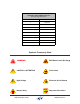
Manual Part Number 7-9469 Copyright © 2009 TX RX Systems, Inc. First Printing: March 2009 Version Number Version Date 1 03/30/09 1.1 06/10/09 Symbols Commonly Used WARNING ESD Electrostatic Discharge CAUTION or ATTENTION Hot Surface High Voltage Electrical Shock Hazard Heavy Lifting Bird Technologies Group NOTE Important Information TX RX Systems Inc.
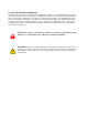
For Class A Unintentional Radiators This equipment has been tested and found to comply with the limits for a Class A digital device, pursuant to Part 15 of the FCC rules. These limits are designed to provide resonable protection against harmful interference when the equipment is operated in a commercial environment.
Table of Contents Overview............................................................................................................... 1 Down / Up Conversion......................................................................................... 2 Unpacking ............................................................................................................ 2 Installation............................................................................................................ 2 Location .......
Changes to this Manual We have made every effort to ensure this manual is accurate. If you discover any errors, or if you have suggestions for improving this manual, please send your comments to our Angola, New York facility to the attention of the Technical Publications Department. This manual may be periodically updated. When inquiring about updates to this manual refer to the manual part number and revision number on the revision page following the front cover.
OVERVIEW Signal boosters extend radio coverage into areas where abrupt propagation losses prevent reliable communication. The system receives an RF signal, raises its power level, and couples it to an antenna so that it can be re-radiated. The input signal may be derived from a receiving antenna or a long run of radiating coax. The TXRX model 611-70 channelized signal booster is designed to operate in the 450 to 470 MHz range.
Down / Up Conversion A channelized signal booster has much in common with a superheterodyne (superhet) receiver. The incoming signal is converted to a lower frequency so that single channel selectivity can be obtained. It is then filtered. Unlike the superhet receiver however, the signal is not demodulated. Instead, it is up-converted back to its original frequency where it is further amplified to reach a useful power level.
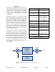
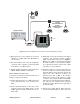
External Antenna (YAGI) Internal Signal Distribution System (Omni-directional Antennas) Signal Generator Isolation (dB) Zero Loss Reference Spectrum Analyzer Figure 2: Typical test equipment interconnection for measuring antenna isolation. 1) Signal generator for the frequencies of interest capable of a 0 dBm output level. Modulation is not necessary. 2) Spectrum analyzer that covers the frequencies of interest and is capable of observing signal levels down to -100 dBm or better.
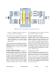
20W PA 20W PA Duplexer/Filter Channel Module - Uplink Channel Module - Downlink Channel Module - Uplink Channel Module - Downlink Active Channel Combiner (one amp per input) Channel Module - Uplink Duplexer/Filter To Donor Antenna Channel Module - Downlink 20W PA Active Receiver Multicoupler Hybrid Combiner Channel Module To Coverage Antenna System Active Receiver Multicoupler Figure 3: Functional block diagram of the channelized signal booster.
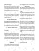
User Interface Connector Power ON LED Indicator Figure 4A: Module housing front view. Figure 4B: Module housing rear view. TX RX Systems Inc. Manual 7-9469-1.
Each branch consists of four boards; Digital, Local Oscillator, Down Converter, and Up Converter. RF signals enter the branch at the down converter board where they are filtered, amplified, and converted into a 70 MHz intermediate frequency. The digital board digitizes the IF signal with an ADC. The digitized samples are applied to a programmable gated array for digital filtering. The filtered signals from the array are converted back into analog by a DAC and output to the up converter board.
Status LED Green (flashing fast) Unit Identification (for several seconds only on command from User Interface) Orange (slow flash) Unprogrammed unit (no settings set) Off Unit disabled (no output from module) Red (slow flash) External reference selected but is absent or not locked Red (solid ON) Alarm of some kind (current or temp out of limits, LO not locked, filter not set) Green (solid ON) all is OK Channel Keyed Slow Flash Unprogrammed unit (no settings set) ON if CTCSS and DCS disabled t
SYSTEMS INC. TX RX Systems Manual 06/10/09 Page 8 TX RX Systems Inc. 8625Inc. Industrial Parkway, Angola, NY 7-9469-1.1 14006 Tel: 716-549-4700 Fax: 716-549-4772 sales@txrx.com www.txrx.