
User's Manual
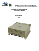
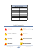
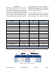
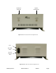
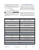
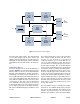
Table Of Contents

TX RX Systems Inc. Manual 7-9470-1.1 04/27/09 Page 3
path configuration with sharp out of band attenua-
tion assuring isolation between the receiving and
transmitting paths. A front and rear view of the unit
are shown in Figures 1A and 1B respectively.
Electrical, mechanical, and environmental specifi-
cations are listed in Table 2.
UNPACKING
It is important to report any visible damage to the
carrier immediately. It is the customer’s responsi-
bility to file damage claims with the carrier within a
short period of time after delivery (1 to 5 days).
Care should be taken when removing the unit from
the packing box to avoid damage to the unit. Use
caution because the heat sink fins can have some-
what sharp corners.
BLOCK DIAGRAM DESCRIPTION
The Series 62 single-band signal booster is a
broadband, bidirectional, dual branch (uplink and
downlink) system. Linear RF active amplifiers, fil-
ters, and DC power sources are used to ade-
quately boost and re-radiate the passband signals.
Signal flow through the system is illustrated using
the system interconnect diagram shown in Figure
2.
The signal booster system is composed of two
symmetrical branches, uplink and downlink. The
only difference between the two branches is the
tuning of their duplexer passbands. The duplexers
isolate the uplink and downlink paths from each
others allowing common connectors to be used for
Electrical Specifications
Passband Gain
80 dB Min (at max output power)
50 db Min (at min output power)
Manual Attenuation Range 0 to 30 dB in 2 dB steps
Passband Ripple +/- 1.5 dB (typical)
Noise Figure 5 dB Max (at 25°C and max gain)
3rd Order Output Intercept Point
Uplink +40 dBm Min
Downlink +52 dBm Min
Input / Output Impedance 50 ohms Nominal
Input / Output VSWR 1.5 : 1.0 (max)
Input Power 80 to 240 VAC at 50 / 60 Hz
Signal Test Ports Optional -50 dB sample signal / additional BNC ports
Alarm Capability Optional Form-C contacts (DB-9 connector)
Mechanical Specifications
Paint Gray Powder-Coat
Dimensions
15.0” x 14.6” x 8.1”
(381 mm x 371 mm x 206 mm)
RF Connectors N-type Female
Weight 30 lBs. (13.63 kg)
Environmental Conditions
This unit is designed for indoor applications
Operating Temperature -30 to +50 °C
Table 2: Series 62 signal booster specifications.