
User's Manual
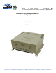
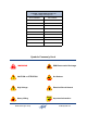
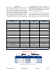
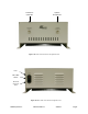
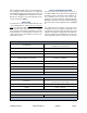
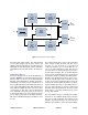
Table Of Contents

TX RX Systems Inc. Manual 7-9470-1.1 04/27/09 Page 1
OVERVIEW
Signal Boosters extend radio coverage into areas
where abrupt RF propagation losses prevent reli-
able communication. No frequency translation
(conversion) occurs with this device. The Series 62
signal booster is a broadband, bi-directional signal
booster that has dual RF paths (uplink and down-
link) to extend coverage in RF shielded environ-
ments. The signal boosters have either a 1 Watt or
10 Watt downlink output level @ 1dB compression
for single band models and either a 2 Watt or 10
Watt downlink output level @ 1 db compression for
dual band models. Table 1 lists all of the models
available as well as their uplink / downlink pass-
bands and downlink output power.
The Series 62 signal booster couples a low noise
figure with a wide dynamic range to provide excel-
lent selectivity for operation in a shared frequency
band. The signal booster is based on a duplexed
Model
Number
Uplink
Band
Downlink
Band
Downlink
Output Power
62-89-A15-01-T3 806 - 821 851 - 866 1 W
62-89-A15-03-T3 806 - 821 851 - 866 10 W
62-90A-A03-01-T3 821 - 824 866 - 869 1 W
62-90A-A03-03-T3 821 - 824 866 - 869 10 W
62-89B-A03-01-T3 806 - 809 851 - 854 1 W
62-89B-A03-03-T3 806 - 809 851 - 854 10 W
62-89A-A18-01-T3 806 - 824 851 - 869 1 W
62-89A-A18-03-T3 806 - 824 851 - 869 10 W
62-88A-A06-01-T3 896 - 902 935 - 941 1 W
62-88A-A06-03-T3 896 - 902 935 - 941 10 W
62-91A-A25-01-T3 824 - 849 869 - 894 1 W
62-91A-A25-03-T3 824 - 849 869 - 894 10 W
62-83E-ADB-02-T3 806 - 824 851 - 869 2 W
62-83E-ADB-04-T3 806 - 824 851 - 869 10 W
62 - 89A - A18 - 03 - T3
(Example)
TYPE
FREQUENCY
BAND
DOWNLINK
OUTPUT
POWERBANDWIDTH
ENCLOSURE
STYLE
62 01 =
02 =
03 =
04 =
1 Watt
2 Watt
10 Watt
10 Watt
A03 =
A06 =
A15 =
A18 =
A25 =
3 MHz
6 MHz
15 MHz
18 MHz
25 MHz
T3 =
Painted
83E
88A
89
89A
89B
90A
91A
764 - 869 MHz
896 - 941 MHz
806 - 866 MHz
806 - 869 MHz
806 - 854 MHz
821 - 869 MHz
824 - 894 MHz
=
=
=
=
=
=
=
Table 1 : Series 62 signal booster models.