
User's Manual
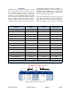
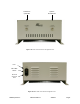
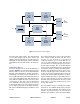
Table Of Contents
Table of Contents Manual 7-9470-1.1 04/27/09
Table of Contents
Overview............................................................................................................... 1
Unpacking ............................................................................................................ 3
Block Diagram Description................................................................................. 4
Front-End Module................................................................................................ 4
Power Amplifier Module....................................................................................... 5
Front Panel Module ............................................................................................. 6
Power Entry/Supply ............................................................................................. 7
Connections......................................................................................................... 8
Alarm Conditions.................................................................................................8
Installation............................................................................................................ 9
Location ............................................................................................................. 9
Mounting .......................................................................................................... 10
Antenna Isolation ............................................................................................. 10
Required Equipment ....................................................................................... 10
Measurement Procedure ................................................................................ 10
Installation Procedure ...................................................................................... 11
Operation............................................................................................................11
Variable Step Attenuator ..................................................................................11
OLC (Automatic Level Control) ......................................................................... 12
RF Exposure ...................................................................................................... 12
Diagnostic Guide ...............................................................................................13
Gain Reduction.................................................................................................. 13
Excessive Intermodulation or Spurious ............................................................. 13
Occasional Drop-out of Some channels ............................................................ 13
Optional Sampler Ports ..................................................................................... 13
Figures and Tables
Figure 1A: Front View of the Unit ........................................................................ 2
Figure 1B: Rear View of the Unit ......................................................................... 2
Figure 2: System Interconnect Diagram ............................................................... 4
Figure 3: Front-End Module Block Diagram ......................................................... 5
Figure 4: Power Amplifier Module Block Diagram ................................................ 6
Figure 5: Front Panel Module Block Diagram....................................................... 7
Figure 6: Power Entry/Supply............................................................................... 7
Figure 7: Remote Alarm Sensing Connector ........................................................ 8
Figure 8: Mechanical Dimensions ....................................................................... 9
Figure 9: Measuring Antenna Isolation...............................................................10
Figure 10: Front Panel ........................................................................................ 12
Table 1: Series 62 Models..................................................................................... 1
Table 2: Specifications .......................................................................................... 3