
User's Manual
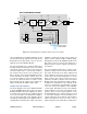
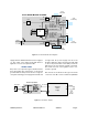
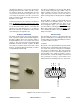
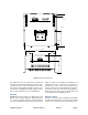
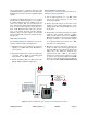
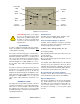

Table Of Contents

TX RX Systems Inc. Manual 7-9470-1.1 04/27/09 Page 12
CAUTION: Operation of the signal
booster at maximum gain with
greater than -20 dBm average power
incident on either of the RF Input
connectors can cause damage to the
signal booster.
RF EXPOSURE
In order to satisfy the FCC RF exposure require-
ments, the signal booster/antenna installation must
comply with the following:
The outdoor antenna (Yagi type or similar direc-
tional antenna) must be installed so as to provide a
minimum separation distance of 1.0 Meters (100
cm or 40 inches) between the antenna and per-
sons within the area. (This assumes a typical
antenna with gain of 10.1 dBi, VSWR < or = 1.5 : 1,
Zo= 50 ohms, and a cable attenuation of between
1-10 dB).
The indoor antenna (omni directional) must be
installed so as to provide a minimum separation
distance of 0.4 Meters (40 cm or 16 inches)
between the antenna and persons within the area.
(This assumes a typical wide-beam type antenna
with gain of 0-2 dBi, VSWR < or = 2 : 1, Zo= 50
ohms, and a cable attenuation of between 1-10
dB).
DIAGNOSTIC GUIDE
The signal booster provides long term, care-free
operation and requires no periodic maintenance.
There are no user-serviceable components inside
the signal booster. This section covers possible
problems that may be related to the installation or
operating environment.
Gain Reduction
Possible causes: bad RF cables, bad RF connec-
tions to antennas or damaged antennas.
Excessive Intermodulation or Spurious
Possible causes: Amplifier oscillation caused by
insufficient isolation. The isolation between two
antennas is given by the equation:
Isolation = 92.5 + 20 Log (F x D) – Gt – Gr
F = frequency (GHz)
Gt = transmit antenna gain (in the direction of the
receive antenna)
D = separation (Km)
Gr = receive antenna gain (in the direction of the
transmit antenna)
For example, at the SMR frequencies, the antenna
isolation at 100 m separation is about 71 dB for
omni-directional antennas (0 dB gain). To increase
isolation, the antennas should have higher directiv-
ity and must be pointed away from each other.
Occasional Drop-out of Some Channels
Possible causes: One channel with very strong
power dominates the RF output of the amplifier.
Optional Sampler Ports
An option is available for the booster that brings
the -50 db sampler ports on the power amplifier
assembly out to the side panel near the RF con-
nectors. This option provides a convenience for
technicians installing or servicing the signal
booster.
Figure 10: The Front Panel.
Power ON
LED
Uplink
Alarm
Rotary
Attenuator
Downlink
Alarm
Downlink
OLC
Uplink
OLC
Rotary
Attenuator