
User's Manual
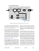
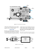
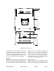
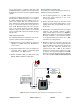
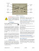

Table Of Contents

TX RX Systems Inc. Manual 7-9470-1.1 04/27/09 Page 11
should exceed the signal booster’s gain fig-
ure by at least 15 dB.
5) Repeat step 4 again with the signal generator
set to frequencies at the passbands edges in
order to see if the isolation is remaining rela-
tively constant over the complete width of the
passband.
6) Repeat the isolation measurements at the other
system passbands to determine the overall min-
imum isolation value for the system. Physical
modification of the antenna system maybe
required in order to reach an acceptable mini-
mum value.
Installation Procedure
To install the signal booster perform the following
in a step-by-step fashion.
CAUTION: DO NOT APPLY A.C.
POWER TO THE SIGNAL
BOOSTER UNTIL CABLES ARE
CONNECTED TO BOTH PORTS OF
THE SIGNAL BOOSTER AND
THE
ANTENNAS.
1. Mount the signal booster on the wall with the RF
connectors pointing DOWN. Using appropriate
screws and anchors, attach the signal booster
to the wall at the six mounting holes on the side
flanges. Refer to figure 8.
2. Ensure that the isolation between the donor
antenna and the service antenna is at least 15
dB greater than the signal booster gain. (Use
the higher of the Uplink and Downlink gains
reported on the test data sheet).
3. Connect the cable from the donor antenna to the
signal booster connector labeled “Uplink Out /
Downlink In” and the cable from the service
antennas to the signal booster connector
labeled “Downlink Out / Uplink In”.
4. Review the attenuator positions on the front of
the signal booster and verify that both of the
attenuator’s are positioned to their maximum
setting (30 dB).
5. Connect the AC power cord to the signal booster
and then to the power source. Move the ON/
OFF switch to the ON position and verify that
the “Power ON” LED is illuminated.
Installation of the signal booster is now complete.
To adjust the gain controls to suit the specific sig-
nal environment, refer to the next section of the
manual.
For repeat installations of existing
equipment, make sure the attenuation
setting is positioned to its maximum
setting (30 dB). After verification of
the attenuation, follow the above
steps starting with step 1.
OPERATION
Power is applied to the unit by turning ON the AC
power switch located on the upper rear of the cabi-
net. The front panel Power Indicator LED should
illuminate. Refer to Figure 10 which is a view of the
front panel.
Variable Step Attenuator
The signal booster gain can be reduced by up to
30 dB in 2 dB steps using the variable step attenu-
ator. Gain adjustments are made with rotary
switches on the front of the unit. The attenuators
are labeled for Uplink and Downlink. Arrows on the
shafts of these switches point to the value of atten-
uation selected. Gain can be determined by sub-
tracting the attenuation value from the gain
reported on the Test Data Sheet for that side of the
unit. A small screwdriver should be used for mak-
ing attenuator adjustments.
OLC (Output Level Control)
To minimize intermodulation products, each
branch in the signal booster contains an OLC feed-
back loop. The OLC circuit senses the output
power and limits it to a factory preset level on the
Uplink and the Downlink.
Red indicator LEDs located on the front panel for
both the uplink and downlink will illuminate when
output power meets or exceeds the OLC factory
preset level.
To establish proper operating gain on the Uplink
and Downlink sides, start with the Downlink.
Observe the downlink OLC indicator LED. Units
are shipped with maximum attenuation. Decrease
the downlink variable attenuator one step at a time
until the downlink OLC lamp is lit. Then increase
the step attenuation until the lamp goes off. Repeat
the process for the Uplink. The OLC indicator LED
is accurate to within +/- 0.4 dB of the OLC factory
preset level.
NOTE