
User's Manual
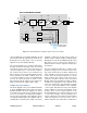
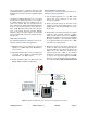
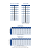

Table Of Contents

TX RX Systems Inc. Manual 7-9470-1.1 04/27/09 Page 10
sary to insure that no conditions exist that could
possibly damage the signal booster and should not
be skipped for even the most thoroughly designed
system.
Just like the feedback squeal that can occur when
the microphone and speaker get too close together
in a public address system, a signal booster can
start to self oscillate. This can occur when the iso-
lation between the Uplink and Downlink antennas
does not exceed the signal boosters gain by at
least 15 dB. Oscillation will reduce the effective-
ness of the system and may possibly damage
amplifier stages. Isolation values are relatively
easy to measure with a spectrum analyzer and sig-
nal generator.
REQUIRED EQUIPMENT
The following equipment is required in order to per-
form the antenna isolation measurements.
1) Signal generator for the frequencies of interest
capable of a 0 dBm output level. Modulation is
not necessary.
2) Spectrum analyzer that covers the frequencies
of interest and is capable of observing signal
levels down to -100 dBm or better.
3) Double shielded coaxial test cables made from
RG142, RG55 or RG223 coaxial cable.
MEASUREMENT PROCEDURE
To measure the antenna isolation perform the fol-
lowing in a step-by-step fashion.
1) Set the signal generator for a 0 dBm output
level at the center frequency of one of the
boosters passbands.
2) Set the spectrum analyzer for the same center
frequency and a sweep width equal to or just
slightly greater than the passband chosen ear-
lier in step 1.
3) Temporarily connect the test leads of the signal
generator and spectrum analyzer together
using a female barrel connector, see Figure 9.
Observe the signal on the analyzer and adjust
the input attenuator of the spectrum analyzer
for a signal level that just reaches the 0 dBm
level at the top of the graticule.
4) Referring to figure 9, connect the generator test
lead to one side of the antenna system and the
spectrum analyzer to the other then observe the
signal level. The difference between this
observed level and 0 dBm is the isolation
between the sections. If the signal is too weak
to observe, the spectrum analyzer’s bandwidth
may have to be narrowed and its input attenua-
tion reduced. The isolation value measured
Signal Generator
External
Antenna
(YAGI)
Spectrum Analyzer
Isolation (dB)
Zero Loss
Reference
Internal
Signal Distribution
System
(Omni-directional
Antennas)
Figure 9: Typical test equipment interconnection for measuring antenna isolation.