
User's Manual
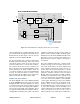
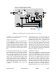
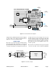
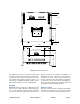
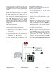
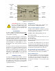
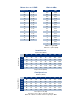

Table Of Contents

TX RX Systems Inc. Manual 7-9470-1.1 04/27/09 Page 9
The signal booster uses external heat sinks and
needs to be mounted such that there can be unob-
structed air flow over the heat sink fins. The cabi-
net will stay warm during normal operation so in
the interest of equipment longevity, avoid locations
that carry hot exhaust air or are continually hot.
Mounting
Figure 8 shows mounting hole dimensions and
layout for the cabinet. Because TX RX Systems,
Inc. cannot anticipate all the possible mounting
locations and structure types where these devices
will be located, we recommend consulting local
building inspectors, engineering consultants or
architects for advice on how to properly mount
objects of this type, size and weight in your particu-
lar situation. It is the customers responsibility to
make sure these devices are mounted safely and
in compliance with local building codes.
Antenna Isolation
Antenna isolation between uplink and downlink
should be measured before connecting the signal
booster to the antenna system. This step is neces-
GAIN REDUCTION
0 . . . 30 dB
GAIN REDUCTION
0 . . . 30 dB
OLC
ALARM
OLC
POWER
ALARM
030 2
16
4
6
28
26
20 18
22
24
1214
10
8
030 2
16
4
6
28
26
20 18
22
24
1214
10
8
DOWNLINK IN
UPLINK OUT
UPLINK IN
DOWNLINK OUT
3.062 3.062
14.624
15.437 0.531
0.750
7.250
13.750
15.000
5.201
8.075
Figure 8: Mechanical dimensions.