
User's Manual
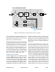
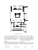
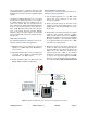
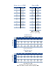

Table Of Contents

TX RX Systems Inc. Manual 7-9470-1.1 04/27/09 Page 8
/ Downlink In” must be connected to the antenna
pointing towards the base station. The RF connec-
tion labeled “Uplink In / Downlink Out” must be
connected to the antenna facing the area to be
covered by the signal booster. RF connections
must be made through cables with characteristic
impedance of 50 ohms.
Isolation between the two antennas should be at
least 15 dB higher than the signal booster gain.
Isolation less than this value can cause gain ripple
across the band. Isolation equal to or less than the
signal booster gain will give rise to oscillations
which will saturate the amplifiers and possibly
cause damage to the signal booster.
ALARMS CONDITIONS
The alarm circuit monitors the current and temper-
ature of both the Uplink and Downlink amplifiers.
An alarm condition will occur if either the Uplink or
Downlink amplifiers are over or under their current
tolerance. The respective front panel alarm LED
will blink to indicate the alarm condition. An OLC
over-range error which causes the booster to shut
down for 10 minutes will be indicated by a continu-
ousely illuminated alarm LED.
An option is available for the booster that allows
remote alarm sensing through a DB-9 connector
which is added to the back of the unit in the lower
right. Customers should connect their remote
alarm sensing cables to this plug. Refer to Figure
7.
Normally Open, Common, and Normally Closed
relay contacts are available at pins 1, 2, and 3
respectively of the DB9 connector. Refer to the
pinout diagram in figure 7. In a Non-Alarm
condi-
tion there will be continuity between the Normally
Open and Common pins. During an Alarm
condi-
tion continuity will switch to the Common and Nor-
mally Closed pins.
INSTALLATION
The following sub-sections of the manual discuss
general considerations for installing the booster. All
work should be performed by qualified personnel in
accordance with local codes.
Location
The layout of the signal distribution system will be
the prime factor in determining the mounting loca-
tion of this unit. However safety and serviceability
are also key considerations. The unit should be
located where it can not be tampered with by the
general public, yet is easily accessible to service
personnel. Also, consider the weight of the unit and
the possibility for injury if it should become
detached from its mounting surface for any reason.
987
24135
6
N.O.
COM.
N.C.
GND
+12V(250mA)
Figure 7: Remote alarm sensing connector.