
User's Manual
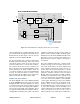
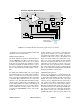
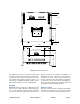
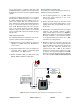
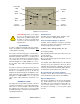
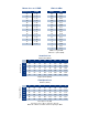

Table Of Contents

TX RX Systems Inc. Manual 7-9470-1.1 04/27/09 Page 7
supply which is illuminated whenever the supply is
on. The output of the supply is 28 VDC which is
applied to J7 on the front panel module.
CONNECTIONS
AC power is accepted through a standard 3-wire
male plug (IEC-320) with phase, neutral and
ground leads. The AC power is wired to a high effi-
ciency DC switching power supply which is CE and
UL approved. The power supply runs all of the
modules within the cabinet and the Power On LED
on the front panel module. This LED provides an
indication to the user that the system is powered.
The metal enclosure of the signal booster is con-
nected to ground.
RF connections are made via two type “N” female
connectors. The RF connector labeled “Uplink Out
PIC
U1
DIP
SW
DIP
SW
UL
Gain Adj
9V
5V
V V A Crl
DL
Gain Adj
UL Temp
UL Curr
DL Curr
9V
V V A Crl
UL PA Temp
DL PA Temp
UL PA Curr
DL PA Curr
UL Driver Curr
DL Driver Curr
DL Temp
Reg
5V
UL OLC
UL ALM
DL ALM
DL OLC
28V
28V
Pwr
PRG
28VDC
Front Panel Module 3-22636
S1
S2
J1
J2
J4
J5
J7
U10
Figure 5: Front Panel Module block diagram.
To UL
Front-End
To DL
Front-End
To DL
Power Amp
To UL
Power Amp
Switching
Power
Supply
Power Entry Module
80-240VAC
28VDC
80-240VAC
EMI Filter
Figure 6: Power Entry / Supply.
To
Front
Panel
Module