
User's Manual
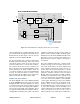
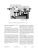
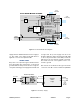
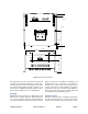
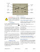
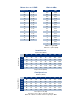

Table Of Contents

TX RX Systems Inc. Manual 7-9470-1.1 04/27/09 Page 6
of regulator U11 on the power amplifier module will
shut down the front-end module.
FRONT PANEL MODULE
The block diagram for the Front Panel Module is
shown in Figure 5. The Microcontroller U1 moni-
tors the temperature and current control inputs
from the front-end and power amplifier modules
and will respond with an alarm whenever a control
line is active. During an alarm the micro will illumi-
nate the appropriate alarm LED (uplink or down-
link).
The uplink and downlink “VVA_CTL” control signal
is passed through the front panel module via ribbon
cable J1 and J2. The microcontroller monitors
these control lines and illuminates either the uplink
or downlink OLC LED whenever the respective
signal is active. The OLC LED will remain lit while
output leveling is taking place. The Output Level
Control (OLC) allows for output power limiting. A
variable step attenuator gives 0 to 30 dB of attenu-
ation in 2 dB steps. The use of these controls are
covered in the “OPERATION” section, later in this
document.
Voltage regulator U10 is used to create bias volt-
ages from the 9 VDC source voltage supplied to
the module through the ribbon cable. The power
amplifier module is the source of the 9 VDC used
by the front panel module. So a malfunction of reg-
ulator U11 on the power amplifier module will shut
down the front panel module. There are two user
adjustable rotary switches located on the front
panel module, S1 for uplink and S2 for downlink.
The rotary switch allows the user to adjust system
gain for the uplink and downlink paths individually
during the installation of the booster.
POWER ENTRY/SUPPLY
The booster is designed to operate between 80
and 240 VAC. Figure 6 shows the block diagram
for the Power Entry Module as well as the Power
Supply. The power entry module has a dual pole
switch for the incoming AC which is followed by a
pair of inline fuses. When operating the booster at
110 VAC one fuse can be replaced by a jumper.
Operation at 220 VAC will require both fuses to be
used. RF interference is reduced by the EMI filter-
ing. The power supply is a switching design that
will operate at either 110 or 220 VAC and is pro-
grammed by jumpers. There is a green LED on the
RF
IN
RF
OUT
-50dB
Port
PA
U4
9V
5V
-20dB
Directional
Coupler U3
9V
5V
Reg
U10
Driver
U2
28V
V V A Control
OLC
Adj
PA Temp
PA Curr
RF
Det
U5
Driver Curr
Temp
Sense
Reg
U11
Curr
Sense
Curr
Sense
PIC
U7
PA Off
9V
PA Off
UL Power Amplifier Module 3-22621
30dB
Pad
U1
U8 U9
U6
Figure 4: Power Amplifier Module block diagram. Uplink shown as an example.
Ribbon Cable to
Front Panel Module