
User's Manual
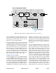
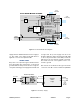
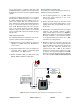
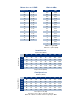

Table Of Contents

TX RX Systems Inc. Manual 7-9470-1.1 04/27/09 Page 5
cation and filtering is provided by amplifier U2 and
low pass filter FL2. RF signals then exit the Front-
End module at the RF output connector and are
applied to the Power Amplifier Module.
The front-end module also contains a Temperature
Sensing and Current Sensing circuit, U11 and U8
respectively. These circuits are used to detect an
excessive temperature or current draw condition.
The output from the sensors are fed back to the
Microcontroller on the Front Panel Module and are
used to determine an alarm condition. There are
four voltage regulators on the Front-End Module
(U9, U6, U7, and U10) which are used to create
bias voltages from the 9 VDC source voltage sup-
plied to the module through the ribbon cable.
POWER AMPLIFIER MODULE
The block diagram for the Power Amplifier Module
is shown in Figure 4. The first stage of the Power
Amplifier Module is the driver amplifier U2. This is
a medium power high linearity amplifier which
serves as a preamp for the high power amplifier.
U4 is the final output high power amplifier. This is
an integrated multi-stage power amplifier with on-
chip impedance matching. The output of the power
amplifier is applied to the directional coupler U3
which is used to sample the OLC feedback signal.
RF signals leave the Power Amplifier Module at the
RF output connector and are then applied to a
duplexer which routes the signals to the appropri-
ate antenna.
The power amplifier module also contains a Tem-
perature sensing circuit U1 and two Current sens-
ing circuits U8 and U9 for the driver amplifier and
power amplifier respectively. These circuits are
used to detect an excessive temperature or current
draw condition. The output from the sensors are
fed back to the Microcontroller on the Front Panel
Module and used to determine an alarm condition.
In addition, the temperature sensor and PA current
sensor are used by the on-board Microcontroller
U7 to turn off the power amplifier via the “PA OFF”
control signal. This will protect the power amplifier
under conditions of excessive current draw or tem-
perature. There are two voltage regulators on the
Front-End Module (U10 and U11) which are used
to create bias voltages from the 28 VDC source
voltage supplied to the module through the ribbon
cable. The regulator U10 is the source of the 9
VDC used by the front-end module. A malfunction
Volt Var Atten
Reg
Reg
Temp
Sense
Amp A
Amp B Amp C
RF
Atten
U4
Curr
Sense
U5
U1
FL1
U2
FL2
U11
U8
U6
U7
U10
U9
9V
V V A Control
Temp
Curr
5VA
5VB
5VC
3.3V
Atten Control
5VB
RF
IN
5VC
5VA
3.3V
RF
OUT
U3
UL Front End Module 3-22620
Figure 3: Front-End Module block diagram. Uplink shown as an example.
Ribbon Cable to
Front Panel Module