
User's Manual
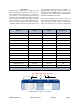
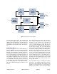
Table Of Contents

TX RX Systems Inc. Manual 7-9470-1.1 04/27/09 Page 4
both input and output signals. The downlink path
receives RF signals from the base station and
amplifies and transmits them to the subscriber. The
uplink path receives RF signals from the subscriber
and amplifies and transmits them to the base sta-
tion.
FRONT-END MODULE
The block diagram for the Front-End Module is
shown in Figure 3. Received RF signals leave the
duplexer and are routed to the Front-End Module
which provides amplification, variable attenuation,
and filtering. U3 is the first stage of amplification on
the Front-End Module and is an LNA with ultra-low
noise figure and high linearity. Following the first
stage LNA is a Digital Attenuator U4. The positive
control inputs for this device are provided by the
user adjustable rotary dip switch located on the
front panel module. The rotary switch allows the
user to adjust system gain for the uplink and down-
link paths individually during the installation of the
booster.
The next functional device on the front-end module
is the voltage variable attenuator U5. The control
voltage for this attenuator is designated
“VVA_CTL” and its source is the RF Detector cir-
cuit on the power amplifier module. The detector
circuit produces an analog voltage proportional to
the RF signal strength. This is an OLC (Output
Level Control) feedback which is incorporated into
the systems design for output power limiting and to
minimize intermodulation products from exces-
sively strong input signal levels. The OLC circuitry
located on the power amplifier module senses the
output power and automatically limits it by adjust-
ing the variable attenuator U5. An LED located on
the front panel module for both the uplink and
downlink channels will illuminate whenever output
power meets or exceeds the OLC factory preset
level for that channel.
The next amplifier stage U1 following the variable
attenuator is a broadband design that incorporates
low noise as well as high IP3. The output from the
amplifier is passed thru the low pass filter FL1
which provides harmonic rejection. Further amplifi-
UL
Front
End
Module
UL
Power
Amplifier
Module
DL
Front
End
Module
DL
Power
Amplifier
Module
Front
Panel
Module
AC
To
Uplink
Antenna
To
Downlink
Antenna
Duplexer
Duplexer
Power Entry
Power Supply
RF
Out
RF
In
RF
Out
RF
In
RF
Out
RF
In
RF
Out
RF
In
TX
RX
RX
TX
Figure 2: System interconnect diagram.