SYSTEMS INC. Installation and Operation Manual for Series 62 Signal Boosters Manual Part Number 7-9470 TX RX Systems Inc. 8625 Industrial Parkway, Angola, NY 14006 Tel: 716-549-4700 Fax: 716-549-4772 sales@txrx.com www.txrx.
Warranty This warranty applies for one year from shipping date. TX RX Systems Inc. warrants its products to be free from defect in material and workmanship at the time of shipment. Our obligation under warranty is limited to replacement or repair, at our option, of any such products that shall have been defective at the time of manufacture. TX RX Systems Inc. reserves the right to replace with merchandise of equal performance although not identical in every way to that originally sold. TX RX Systems Inc.
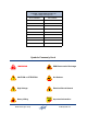
Manual Part Number 7-9470 Copyright © 2008 TX RX Systems, Inc. First Printing: February 2009 Version Number Version Date 1 02/14/09 1.1 04/27/09 Symbols Commonly Used WARNING ESD Electrostatic Discharge CAUTION or ATTENTION Hot Surface High Voltage Electrical Shock Hazard Heavy Lifting Bird Technologies Group NOTE Important Information TX RX Systems Inc.
For Class A Unintentional Radiators This equipment has been tested and found to comply with the limits for a Class A digital device, pursuant to Part 15 of the FCC rules. These limits are designed to provide resonable protection against harmful interference when the equipment is operated in a commercial environment.
Table of Contents Overview............................................................................................................... 1 Unpacking ............................................................................................................ 3 Block Diagram Description................................................................................. 4 Front-End Module ................................................................................................ 4 Power Amplifier Module....
Changes to this Manual We have made every effort to ensure this manual is accurate. If you discover any errors, or if you have suggestions for improving this manual, please send your comments to our Angola, New York facility to the attention of the Technical Publications Department. This manual may be periodically updated. When inquiring about updates to this manual refer to the manual part number and revision number on the revision page following the front cover.
for single band models and either a 2 Watt or 10 Watt downlink output level @ 1 db compression for dual band models. Table 1 lists all of the models available as well as their uplink / downlink passbands and downlink output power. OVERVIEW Signal Boosters extend radio coverage into areas where abrupt RF propagation losses prevent reliable communication. No frequency translation (conversion) occurs with this device.
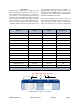
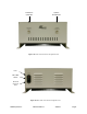
Uplink In Downlink Out Downlink In Uplink Out Figure 1A: Front view of the Series 62 signal booster. Fuse ON / OFF Switch AC Cord Connects Here Figure 1B: Rear view of the Series 62 signal booster. TX RX Systems Inc. Manual 7-9470-1.
path configuration with sharp out of band attenuation assuring isolation between the receiving and transmitting paths. A front and rear view of the unit are shown in Figures 1A and 1B respectively. Electrical, mechanical, and environmental specifications are listed in Table 2. UNPACKING It is important to report any visible damage to the carrier immediately. It is the customer’s responsibility to file damage claims with the carrier within a short period of time after delivery (1 to 5 days).
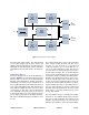
RF In UL Front RF Out End Module RF In UL Power RF Amplifier Out Module TX Duplexer To Uplink Antenna RX Power Entry Front Panel Module AC Power Supply RX Duplexer To Downlink Antenna TX RF In DL Front RF Out End Module DL Power RF RF In Amplifier Out Module Figure 2: System interconnect diagram. both input and output signals. The downlink path receives RF signals from the base station and amplifies and transmits them to the subscriber.
UL Front End Module 3-22620 3.3V 5VA RF IN 5VB 5VC RF OUT RF Atten U4 Amp A U3 Volt Var Atten U5 Amp B U1 Amp C U2 FL1 FL2 V V A Control Atten Control U9 3.3V Reg 5VA 5VB 5VC Reg Temp Sense U11 U6 U7 U10 Curr Sense U8 Temp Curr 9V Ribbon Cable to Front Panel Module Figure 3: Front-End Module block diagram. Uplink shown as an example. cation and filtering is provided by amplifier U2 and low pass filter FL2.
UL Power Amplifier Module 3-22621 5V 9V RF IN Driver U2 PA U4 PA Off -20dB Temp Sense U1 Curr Sense U8 RF OUT Directional Coupler U3 Curr Sense U9 RF Det U5 PIC U7 OLC Adj 30dB Pad -50dB Port U6 V V A Control 5V 9V PA Off PA Temp PA Curr Driver Curr Reg U10 9V Reg U11 28V Ribbon Cable to Front Panel Module Figure 4: Power Amplifier Module block diagram. Uplink shown as an example. of regulator U11 on the power amplifier module will shut down the front-end module.
To UL Front-End Front Panel Module 3-22636 UL DIP Gain Adj SW U10 5V J4 To UL Power Amp S1 28V Reg UL Temp UL Curr UL PA Temp UL PA Curr UL Driver Curr 5V UL UL DL DL OLC ALM OLC ALM PIC U1 DL Driver Curr DL PA Curr DL PA Temp DL Curr DL Temp PRG Pwr 28VDC DL DIP Gain Adj SW J7 9V V V A Crl J2 J1 V V A Crl 9V 28V S2 To DL Power Amp J5 To DL Front-End Figure 5: Front Panel Module block diagram. supply which is illuminated whenever the supply is on.
/ Downlink In” must be connected to the antenna pointing towards the base station. The RF connection labeled “Uplink In / Downlink Out” must be connected to the antenna facing the area to be covered by the signal booster. RF connections must be made through cables with characteristic impedance of 50 ohms. Isolation between the two antennas should be at least 15 dB higher than the signal booster gain. Isolation less than this value can cause gain ripple across the band.
.000 13.750 POWER 7.250 OLC 28 30 0 ALARM 2 26 OLC 4 28 30 0 6 26 24 8 22 10 ALARM 2 4 6 24 8 22 10 20 18 16 14 12 20 18 16 14 12 GAIN REDUCTION GAIN REDUCTION 0 . . . 30 dB 0 . . . 30 dB 0.750 15.437 0.531 14.624 3.062 3.062 DOWNLINK IN UPLINK OUT UPLINK IN DOWNLINK OUT 8.075 5.201 Figure 8: Mechanical dimensions. The signal booster uses external heat sinks and needs to be mounted such that there can be unobstructed air flow over the heat sink fins.
MEASUREMENT PROCEDURE To measure the antenna isolation perform the following in a step-by-step fashion. sary to insure that no conditions exist that could possibly damage the signal booster and should not be skipped for even the most thoroughly designed system. 1) Set the signal generator for a 0 dBm output level at the center frequency of one of the boosters passbands.
should exceed the signal booster’s gain figure by at least 15 dB. 5) Repeat step 4 again with the signal generator set to frequencies at the passbands edges in order to see if the isolation is remaining relatively constant over the complete width of the passband. 6) Repeat the isolation measurements at the other system passbands to determine the overall minimum isolation value for the system. Physical modification of the antenna system maybe required in order to reach an acceptable minimum value.
Power ON LED Downlink OLC Uplink Alarm Uplink OLC Downlink Alarm Rotary Attenuator Rotary Attenuator Figure 10: The Front Panel. CAUTION: Operation of the signal booster at maximum gain with greater than -20 dBm average power incident on either of the RF Input connectors can cause damage to the signal booster.
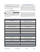
Return Loss vs. VSWR Watts to dBm Return Loss VSWR Watts dBm 30 1.06 300 54.8 25 1.11 250 54.0 20 1.20 200 53.0 19 1.25 150 51.8 18 1.28 100 50.0 17 1.33 75 48.8 16 1.37 50 47.0 15 1.43 25 44.0 14 1.50 20 43.0 13 1.57 15 41.8 12 1.67 10 40.0 11 1.78 5 37.0 10 1.92 4 36.0 9 2.10 3 34.8 2 33.0 1 30.
SYSTEMS INC. RX Systems Manual 14 TX RX TX Systems Inc. 8625Inc. Industrial Parkway, Angola, NY7-9470-1.1 14006 Tel: 716-549-4700 Fax: 04/27/09 716-549-4772 sales@txrx.com Page www.txrx.