
User's Manual

Manual 7-9410-1.2 Page 8
TX RX Systems Inc. 10/21/05
61-83B-50-XXX-XX UserMan page 8 of 25
spectrum analyzer or a laptop computer from time
to time. The location of the power source will also
have a bearing on the mounting location. SB II
uses external heat sinks and needs to be mounted
where there can be an unobstructed air flow over
the heat sinks fins. The SB II cabinet will stay warm
during normal operation so in the interest of equip-
ment longevity, avoid locations that carry hot
exhaust air or are continually hot.
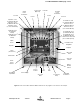
Mounting
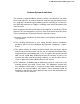
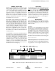
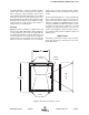
Figure 1 shows mounting hole dimensions and
layout for the cabinet. Mount the cabinet using 3/8”
(10 mm) diameter steel bolts (not supplied). We
recommend flat washers on both ends and a lock
washer under the nut. Nut and bolt mounting is
preferred to the use of lag bolts. Use backer blocks
where necessary to spread the force over a larger
surface area. In areas of known seismic activity,
additional devices such as tether lines may be nec-
essary.
Because TX RX Systems, Inc. cannot anticipate all
the possible mounting locations and structure
types where these devices will be located, we rec-
ommend consulting local building inspectors, engi-
neering consultants or architects for advice on how
to properly mount objects of this type, size and
weight in your particular situation.
It is the cus-
tomer’s responsibility to make sure these
devices
are mounted safely and in compliance with local
building codes.
CONNECTIONS
All cabling connections to the booster should be
made and checked for correctness prior to power-
ing up the system.
MOUNTING TABS
DOOR
CLAMPS
0.438" DIA.
(12mm)
0.438" DIA.
(12mm)
SIDE VIEW
18"
(457mm)
21.25"
(540mm)
Figure 1: SB II cabinet mounting hole layout.