
User's Manual

Manual 7-9410-1.2 Page 7
TX RX Systems Inc. 10/21/05
61-83B-50-XXX-XX UserMan page 7 of 25
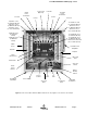
GENERAL DESCRIPTION
Signal boosters extend radio coverage into areas
where abrupt propagation losses prevent reliable
communication. No frequency translation (conver-
sion) occurs with this device. Signal Booster II (SB
II) is a broadband, bi-directional signal booster
available in a variety of configurations as shown in
Table 1. The product model number is used to
describe each configuration available. This manual
details the installation and operation of the 61-83B-
50-XXX-XX series of boosters.
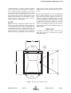
The system can be ordered in one of three maxi-
mum gain configurations including Full Gain (+80
dB gain max), Medium Gain (+60 dB gain max),
and Low Gain (+45 dB max gain). The maximum
gain of the system is determined by the exact type
of cards plugged into the low and mid level slots as
shown in the block diagrams at the back of this
manual. The maximum gain of the uplink or down-
link branch is adjustable and can be setup inde-
pendently. In addition, the gain of each branch can
be reduced up to 30 dB in 0.5 dB increments via
software interface.
The bandwidth of the system is determined by the
passband of the input/output filtering. The filters
passband is determined by its physical construc-
tion. Three cabinet styles are available. The G1
suffix denotes a NEMA-4 style cabinet which is
suitable for indoor or outdoor use. The G2 suffix
denotes a stainless steel NEMA-4X style cabinet
suitable for corrosive environments such as salt air
and the RM suffix a rack mount version which is
intended for indoor mounting only.
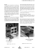
UNPACKING
It is important to report any visible damage to the
carrier immediately. It is the customer's responsi-
bility to file damage claims with the carrier within a
short period of time after delivery (1 to 5 days).
Care should be taken when removing the unit from
the packing box to avoid damage to external heat-
sink fins. Use caution because the heatsink fins
can have somewhat sharp corners. Signal Booster
II (SB II) weighs about 85 lbs. so use enough peo-
ple when lifting the unit.
INSTALLATION
The following sections discuss general consider-
ations for installing the booster. All work should be
performed by qualified personnel in accordance
with local codes.
Location
The layout of the signal distribution system will be
the prime factor in determining the mounting loca-
tion of Signal Booster II. However, safety and ser-
viceability are also key considerations. The unit
should be located where it cannot be tampered
with by the general public, yet is easily accessible
to service personnel. Also consider the weight of
the unit and the possibility for injury if the unit
should become detached from its mounting sur-
faces for any reason.
Although signal boosters can operate for years
without being attended to, the unit will need to be
accessed by service personnel with troubleshoot-
ing equipment, such as digital multimeters and
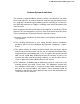
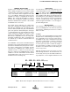
61 - 83B - 50 - A12 - G1
(Example)
*
FAMILY FREQUENCY
BAND
MODEL COARSE
GAIN
BANDWIDTH ENCLOSURE
TYPE
60 =
61 =
612 =
1 Way
2 Way
2 Way
w/Fiber
Interface
83B = 764 - 776
794 - 806
50 = Signal
Booster II
A =
B =
C =
80 dB
60 dB
45 dB
12 = 12 MHz G1 =
G2 =
RM =
Painted, Nema4
Stainless, Nema4X
Rack Mount
*
Note: Gain of 80 dB model set to 50 dB at factory. Please measure antenna isolation before resetting.
Table 1: Model number designations. Model 61-83B-50-A12-G1 shown as example.
GAI