
User's Manual

61-83B-50-XXX-XX UserMan page 6 of 25
Manual 7-9410-1.2 10/21/05
Table of Contents
Figures and Tables
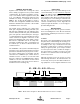
Figure 1 Cabinet mounting hole layout 8
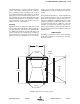
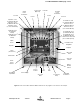
Figure 2 Front internal cabinet view 9
Figure 3 AC line entry 10
Figure 4 Connecting the battery backup voltage 10
Figure 5 Measuring antenna isolation 12
Figure 6 Boot-up display 12
Figure 7 Operational status display 13
Figure 8 Menu System 14
Figure 9 Measuring Booster Gain 17
Figure 10 Performance Survey 18
Figure 11 Removing the Power Amplifier (1 of 3) 19
Figure 12 Removing the Power Amplifier (2 of 3) 20
Figure 13 Removing the Power Amplifier (3 of 3) 20
Figure 14 Disconnecting Display/User Interface 21
Figure 15 Preselector Tuning 23
Table 1 Model Number Designations 7
Specifications 24
Celsius to Fahrenheit Conversions 25