
User's Manual

Manual 7-9410-1.2 Page 23
TX RX Systems Inc. 10/21/05
61-83B-50-XXX-XX UserMan page 23 of 25
been physically damaged or are tampered with.
Combline preselector filters provide the input and
output selectivity for the system. These filters have
a carefully shaped response curve that passes a
number of contiguous communication channels
with each filter designed to cover a 12 MHz band-
width.
TEST EQUIPMENT
A two channel network analyzer that simulta-
neously displays both transmission and reflection
is best for properly tuning a preselector. A single
channel tracking generator/spectrum analyzer
combination may be adequate but is not accurate
enough to verify factory specifications. A return
loss bridge would also be required when using a
tracking generator. Skill and experience are also
needed and the personnel doing the work should
be thoroughly familiar with the use of the network
analyzer. A Hewlett Packard 8752B or equivalent
network analyzer is recommended.
PRESELECTOR TUNING
The following is a general outline of the tuning pro-
cedure.
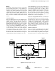
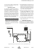
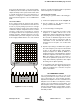
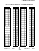
1) Connect test equipment as shown in Figure 15.
2) Set the analyzer to the desired center fre-
quency and desired bandwidth.
3) Loosen the tuning rod locking nuts.
4) If the preselector is severely out of tune, set the
analyzer for 10 dB/div vertical scale on the
transmission channel and alternately adjust the
tuning rods in pairs working from the center to
the end rods for maximum signal at the center
frequency. Note that for preselectors with an
odd number of rods, start with the center rod
and then move to the pairs, one on either side
of center.
5) Repeat step 4 tuning to maximize the signal at
the center frequency. The response should start
to take on the desired shape and symmetry.
Setup the analyzer for 1 dB/div (2 dB/div for a
tracking generator) on the transmission channel
and then re-adjust the rods in the same fashion.
Make sure that the return loss curve meets or
exceeds the published specification over the
range and is relatively symmetrical. Fine adjust
the tuning rods to adjust symmetry.
7) Lock all tuning rods after the desired response
is obtained. Note that a slight dissymmetry in
either the transmission or reflection response
may be unavoidable.
RECOMMENDED SPARES
It is recommended that one spare of each of the
following assemblies be kept on hand for emer-
gency repair purposes; Power Supply 8-20667,
Uplink Power Amplifier 3-21121, Downlink Power
Amplifier 3-2119, Mid Level Amplifier Card 3-
19576, Low Level Amplifier Card 3-19575, Low
Gain Amplifier Card 3-20294, Attenuator Card 3-
20208, Power Distribution Card 3-19833, Control-
ler Card 3-19832, and the Display/User Interface
Assembly 3-19831.
Analyzer
Input
Generate
Output
+30
+40
+20
+10
0
-10
-20
-30
-40
8 Section Combline
Bandpass Filter
Figure 15: Preselector Tuning.