
User's Manual

Manual 7-9410-1.2 Page 21
TX RX Systems Inc. 10/21/05
61-83B-50-XXX-XX UserMan page 21 of 25
card cage. Once the card is seated into place
properly tighten the thumb screws.
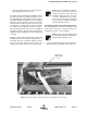
The SB II low level and mid level amplifier stages
are field replaceable by simply removing the mod-
ule and plugging in a replacement. These modules
are HOT switchable meaning they can be swapped
without powering down the system. RF cables
attached to the modules must be removed (5/16”
wrench) prior to swapping the modules and must
be re-attached after the new module is in place.
when replacing the RF cables do not overtighten
the SMA connectors. They should be tightened just
slightly more than hand tight or to the specification
of 7 in/lbs.
Modules can be swapped between the uplink and
downlink branches for troubleshooting purposes. If
a problem exists in one branch and the problem
moves to the other branch when modules are
swapped around this indicates a defective module.
Note: After an amplifier module is
replaced use the Calibrate Currents
software function to properly set the
amplifiers alarm trip point, see page
10. Due to slight differences in compo-
nent tolerances the trip point must be
reset for any new amplifier assemblies
introduced into the system.
Display/User Interface Assembly Replacement
The SB II Display/User Interface assembly is field
replaceable. Follow the steps listed below in
sequential order. No tools are required.
Note: Power to the SB II cabinet must
be turned OFF during the display/user
interface replacement process.
1) Loosen the two thumb-nuts which hold the dis-
play/user interface assembly to the card cage.
NOTE
NOTE
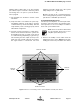
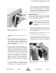
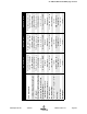
Figure 14: Disconnecting the display/user interface assembly from the card cage.
Disconnect
ribbon cable
here