
User's Manual

Manual 7-9410-1.2 Page 19
TX RX Systems Inc. 10/21/05
61-83B-50-XXX-XX UserMan page 19 of 25
lightning strikes, failures may occur. The following
procedures may be followed for detecting a mal-
functioning unit or as part of a periodic mainte-
nance program.
1) The heatsink area should be cleared of dust
and debris.
2) Inspect the unit to see that the two power sup-
ply LED DC indicators are lit (remove any dust
or debris that may obscure the LEDs). This will
verify that DC power is flowing properly. Check
all hardware for tightness.
3) Compare system performance to initial perfor-
mance levels measured when the system was
first installed. The lack of signal can be traced
to a malfunctioning amplifier by progressive sig-
nal monitoring from the output (far end) to the
input end of the system noting the area where
the signal returns to normal level. The next
amplifier toward the output end of the system
will probably be the one that failed.
or
Measure the gain at any convenient frequency
in the working frequency band to verify that the
performance is still within specifications.
Power Amplifier Replacement
The SB II power amplifiers are field replaceable.
Follow the steps listed below in sequential order.
The required tools are a #1 Phillips screwdriver
and a 5/16” open-ended wrench.
Note: Power to the SB II cabinet must
be turned OFF during the power
amplifier replacement process.
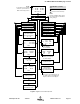
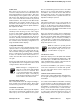
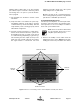
1) Remove the Phillips screws which hold the
amplifier into place, refer to Figure 11. The nuts
holding the screws are pressed into the cabinet
NOTE
Figure 11: Remove 14 mounting screws to detach amplifier assembly from cabinet.
Remove Screws
Remove Screws
Remove
Screws
Remove
Screws