
User's Manual

Manual 7-9410-1.2 Page 10
TX RX Systems Inc. 10/21/05
61-83B-50-XXX-XX UserMan page 10 of 25
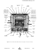
AC Line
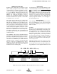
Signal Booster II is designed to be hard-wired to
110 single phase AC lines at 50 - 60 Hz (see Fig-
ures 2 and 3). An AC line filter is provided for this
purpose. There is a hole provided in the cabinet
bottom-wall for bringing in the AC line. Fasten
quick connect plugs to each wire of the incoming
AC line, then connect the ground wire and hot wire
to the respective pins on the top of the AC line filter
assembly. Refer to the photo shown in figure 3.
The output of the AC line filter is wired into the
switch box which also contains a dual convenience
outlet for running test equipment. Use conduit for
running the AC line into the SBII cabinet and use
#14 gauge or large conductors.
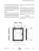
Backup DC Power
SB II may be run on a DC power source that can
supply 24 to 27 volts DC at 2.5 amps (see Figures
2 and 4). This source should be equipped with a
fast-acting 3 Amp fuse. A DC line filter is provided
for making the connection inside the unit. There is
a hole provided in the cabinet bottom-wall for bring-
ing in the DC supply. Fasten spade lugs to each
wire of the incoming DC and then connect to the
respective pins on the DC line filter assembly.
Refer to the photo shown in figure 4. Use #16 or
#18 gauge wire for this connection. The power sys-
tem in SB II automatically switches to this backup
DC input when the AC supply fails for any reason
including a power outage or intentional disconnec-
tion.
It is not necessary that this connection be made for
normal operation on the AC line.
Alarm Terminals (Form-C contacts)
Two sets of contacts are provided to monitor the
general operating condition of SB II and are
intended for connection to a supervisory system.
See figure 2.
One set changes state when the AC power supply
shuts down for any reason and the unit switches to
operation on the backup DC power system. The
other set of contacts changes state when any of a
number of fault conditions arises within the elec-
tronics such as current drain outside of the
expected operating range in some module.
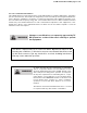
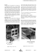
Figure 3: Wiring of AC line entry.
Connect incoming AC
line to the input lugs of
the AC line filter
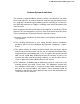
Connect incoming battery
backup to the input screws
on the DC filter
Figure 4: Battery Backup connections.