61-83B-50-XXX-XX UserMan page 1 of 25 Part No. 7-9410-1.2 Installation and Operation Manual for the Two-Way Signal Booster System Model Number 61-83B-50-XXX-XX Copyright © 2005 TX RX Systems Inc. First Printing: July 2005 Version Number Version Date 1 07/20/05 1.1 09/19/05 1.
61-83B-50-XXX-XX UserMan page 2 of 25 Warranty Symbols This warranty applies for one year from shipping date. Commonly Used TX RX Systems Inc. warrants its products to be free from defect in material and workmanship at the time of shipment. Our obligation under warranty is limited to replacement or repair, at our option, of any such products that shall have been defective at the time of manufacture. TX RX Systems Inc.
61-83B-50-XXX-XX UserMan page 3 of 25 For Class A Unintentional Radiators This equipment has been tested and found to comply with the limits for a Class A digital device, pursuant to part 15 of the FCC rules. These limits are designed to provide reasonable protection against harmful interference when the equipment is operated in a commercial environment.
61-83B-50-XXX-XX UserMan page 4 of 25 Antenna System Installation The antenna or signal distribution system consists of two branches. An uplink branch typically uses an outdoor mounted, unidirectional gain antenna such as a yagi and a downlink signal radiating system consisting of a network of zero-gain whip antennas or lengths of radiating cable usually mounted inside of the structure. Even though the antenna system may not be supplied or installed by TX RX Systems.
61-83B-50-XXX-XX UserMan page 5 of 25 Table of Contents General Description .............................................................................................. 7 Unpacking ....................................................................................................... 7 Installation ....................................................................................................... 7 Location ..............................................................................................
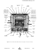
1-83B-50-XXX-XX UserMan page 6 of 25 Figures and Tables Figure 1 Figure 2 Figure 3 Figure 4 Figure 5 Figure 6 Figure 7 Figure 8 Figure 9 Figure 10 Figure 11 Figure 12 Figure 13 Figure 14 Figure 15 Cabinet mounting hole layout Front internal cabinet view AC line entry Connecting the battery backup voltage Measuring antenna isolation Boot-up display Operational status display Menu System Measuring Booster Gain Performance Survey Removing the Power Amplifier (1 of 3) Removing the Power Amplifier (2 of 3) Re
61-83B-50-XXX-XX UserMan page 7 of 25 GENERAL DESCRIPTION Signal boosters extend radio coverage into areas where abrupt propagation losses prevent reliable communication. No frequency translation (conversion) occurs with this device. Signal Booster II (SB II) is a broadband, bi-directional signal booster available in a variety of configurations as shown in Table 1. The product model number is used to describe each configuration available.
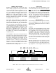
61-83B-50-XXX-XX UserMan page 8 of 25 spectrum analyzer or a laptop computer from time to time. The location of the power source will also have a bearing on the mounting location. SB II uses external heat sinks and needs to be mounted where there can be an unobstructed air flow over the heat sinks fins. The SB II cabinet will stay warm during normal operation so in the interest of equipment longevity, avoid locations that carr y hot exhaust air or are continually hot.
61-83B-50-XXX-XX UserMan page 9 of 25 Uplink Power Distribution Test Port Comm-Card (Optional) Controller Downlink Power Distribution Isolator Isolator Test Port Uplink L/L Card (for Full Gain Model) Attenuator Card (for Mid Gain Model) Attenuator Card (for Low Gain Model) Downlink L/L Card (for Full Gain Model) Attenuator Card (for Mid Gain Model) Attenuator Card (for Low Gain Model) Uplink M/L Card (for Full Gain Model) Uplink M/L Card (for Mid Gain Model) Downlink M/L Card (for Full Gain Model
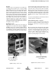
61-83B-50-XXX-XX UserMan page 10 of 25 AC Line Signal Booster II is designed to be hard-wired to 110 single phase AC lines at 50 - 60 Hz (see Figures 2 and 3). An AC line filter is provided for this purpose. There is a hole provided in the cabinet bottom-wall for bringing in the AC line. Fasten quick connect plugs to each wire of the incoming AC line, then connect the ground wire and hot wire to the respective pins on the top of the AC line filter assembly. Refer to the photo shown in figure 3.
61-83B-50-XXX-XX UserMan page 11 of 25 A six-terminal strip is provided for the interface and uses screw terminals for ease of connection. Route the alarm wires through one of the access holes in the bottom of the box, strip about 3/16” of insulation from each end, loosen the screw terminal, insert and retighten. Use #20 or #22 gauge insulated wire. Use of these terminals is optional. SB II also has a number of status LEDs built-in to individual modules to indicate a fault condition.
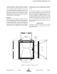
61-83B-50-XXX-XX UserMan page 12 of 25 EXTERNAL ANTENNA INTERNAL SIGNAL DISTRIBUTION SYSTEM SPECTRUM ANALYZER SIGNAL GENERATOR ISOLATION (dB) ZERO LOSS REFERENCE Figure 5: Typical test equipment interconnection for measuring antenna isolation. It is wise to repeat the procedure listed above for measuring antenna isolation with the signal generator set to frequencies at the passbands edges in order to see if the isolation is remaining relatively constant over the complete width of the passband.
61-83B-50-XXX-XX UserMan page 13 of 25 1) At turn-on, the four status LEDs on the front panel glow red for about 5 seconds as the result of entering a self-check mode. FRONT PANEL LEDS: 24V: Green indicates the 24 volt DC Power system is operating properly. 2) The two green OLC light bars will be fully lit along their length for approximately 5 seconds. 12V: Green indicates the 12 volt DC power system is operating properly.
61-83B-50-XXX-XX UserMan page 14 of 25 NOTE: If no button is pressed within 2 minutes, system returns to Main Status Display Screen UL: DL: GAIN ## dB ## dB SBII USER MENU 1 (8-20460B) OUT LVL ## dBm ## dBm KEY E Press ENTER key SBII Status OK Press Item Select arrow key E Detailed Status Calibrate Currents Uplink Low Level Amp Set Gain Uplink Mid Level Amp E Set Output Level E E E E Configuration E E NOTE: Pressing CANCEL always returns you to the previous menu without saving changes
61-83B-50-XXX-XX UserMan page 15 of 25 LCD Screen Once the boot-up sequence is completed (after several seconds) the LCD screen will switch to the main status display as shown in figure 7. This is the normal display for the signal booster. The system will return to this display from any other display if none of the menu interface buttons are pressed within 2 minutes. The exception is the OLC status display which does require a button press to exit.
61-83B-50-XXX-XX UserMan page 16 of 25 Low and the Enter key toggles the gain setting. The corresponding gain level is displayed. Select Done using the arrow keys and press enter to return to the menu. Use the Cancel button to return to the Status Display. Detailed Status Screens These items allow a detailed examination of system components including; all amplifiers (current draw and temperature), the power supply (voltage level), and the OLC function (present status and historical archive).
61-83B-50-XXX-XX UserMan page 17 of 25 Alarms The system continuously monitors the current draw and operating temperature of each amplifier as well as the voltage level of the +12 and +24 VDC supplies. If any of these parameters exceed normal operating levels by a factory preset percentage the system enters an alarm condition. Notification of an alarm condition is provided by LED indicators and Form-C contacts available via the alarm terminal screws.
61-83B-50-XXX-XX UserMan page 18 of 25 tion of any alarm condition occurring and the second set of contacts indicate the system is operating on battery backup power. PERFORMANCE SURVEY It is a good idea to document the performance of the system after installation so that a reference exists for future comparisons. This information can make troubleshooting an interference problem or investigation of a complaint about system performance much easier.
61-83B-50-XXX-XX UserMan page 19 of 25 lightning strikes, failures may occur. The following procedures may be followed for detecting a malfunctioning unit or as part of a periodic maintenance program. 1) The heatsink area should be cleared of dust and debris. 2) Inspect the unit to see that the two power supply LED DC indicators are lit (remove any dust or debris that may obscure the LEDs). This will verify that DC power is flowing properly. Check all hardware for tightness.
61-83B-50-XXX-XX UserMan page 20 of 25 nectors. They should be tightened just slightly more than hand tight or to the specification of 7 in/lbs. The replacement amplifier comes with an attached gasket which must press up against the outside of the cabinet firmly and squarely in order to provide a correct moisture seal. Module Replacement The SB II modules are field replaceable. Follow the steps listed below in sequential order. The required tools are a #1 Phillips screwdriver.
61-83B-50-XXX-XX UserMan page 21 of 25 card cage. Once the card is seated into place properly tighten the thumb screws. The SB II low level and mid level amplifier stages are field replaceable by simply removing the module and plugging in a replacement. These modules are HOT switchable meaning they can be swapped without powering down the system. RF cables attached to the modules must be removed (5/16” wrench) prior to swapping the modules and must be re-attached after the new module is in place.
61-83B-50-XXX-XX UserMan page 22 of 25 2) Gently tilt only the top of the assembly up from the card cage. Keep the bottom of the assembly in place. The bottom mounting plate (part of the card cage) has an overhang on it to support the display/user interface board. If the assembly is lifted straight out the overhang it could possibly damage the interface circuit board. 3) With the display/user interface board standing up straight gently move it upwards while lifting it out about an inch or two.
61-83B-50-XXX-XX UserMan page 23 of 25 been physically damaged or are tampered with. Combline preselector filters provide the input and output selectivity for the system. These filters have a carefully shaped response curve that passes a number of contiguous communication channels with each filter designed to cover a 12 MHz bandwidth. analyzer. A Hewlett Packard 8752B or equivalent network analyzer is recommended. PRESELECTOR TUNING The following is a general outline of the tuning procedure.
TX RX Systems Inc. 10/21/05 Net Weight: Nominal Size: Housing: < 85 lbs. < 85 lbs. 24" x 24" x 8" NEMA 4, NEMA 4X Rack Mount NEMA 4, NEMA 4X Rack Mount 24" x 24" x 8" <150 VA +24 to +27 VDC 100-240 VAC; 50-60 Hz BNC female N female 50 ohms, <1.5:1 VSWR -30°C to +50° C 3.5 dB maximum <150 VA +24 to +27 VDC DC Input Voltage: Unit Power Consumption (AC/DC): 100-240 VAC; 50-60 Hz BNC female RF Sampler Connectors: AC Power Input: N female Input/Output Connectors: 50 ohms, <1.
61-83B-50-XXX-XX UserMan page 25 of 25 CELSIUS TO FAHRENHEIT CONVERSION TABLE CELCIUS FARENHEIT CELCIUS FARENHEIT CELCIUS FARENHEIT CELCIUS FARENHEIT 105 221.0 66 150.8 27 80.6 -12 10.4 104 219.2 65 149.0 26 78.8 -13 8.6 103 217.4 64 147.2 25 77.0 -14 6.8 102 215.6 63 145.4 24 75.2 -15 5.0 101 213.8 62 143.6 23 73.4 -16 3.2 100 212.0 61 141.8 22 71.6 -17 1.4 99 210.2 60 140.0 21 69.8 -18 -0.4 98 208.4 59 138.2 20 68.0 -19 -2.2 97 206.