User's Manual
Table Of Contents
- Installation and Operation Manual
- Table of Contents
- Introduction
- Installation
- Cautionary Notes
- Pre-RF Connection Tests
- OPERATION
- Signal flow
- System Components
- Field Adjustments
- Maintenance and Repair
- Recommended replacement parts
- Conversion Chart

61-38-05 UserMan page 30 of 38
TXRX Systems Inc. Manual 7-9408-1.2 07/25/05 Page 30
5) Engage the Input Tuning Capacitors one at a
time and rotate them for maximum gain.
NOTE:
If the gain peaks at a level
about 60% of maximum, one of the
variable capacitors should be rotated
180° and steps 4 and 5 repeated.
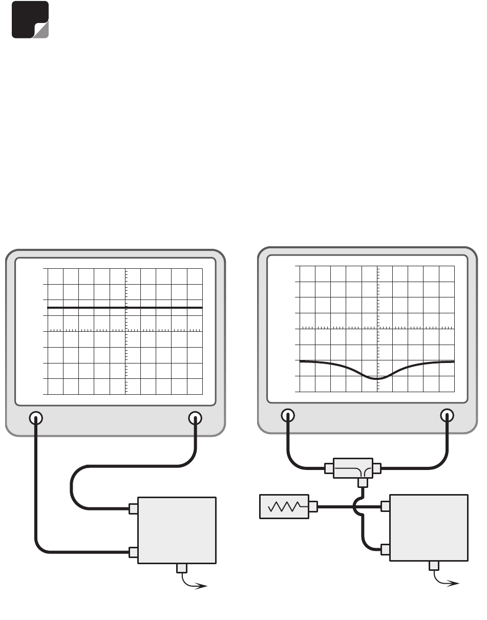
6)Connect the return loss bridge to
the tracking generator as shown in
Figure 22
but do not connect it to the
amplifier. Leave the test port on the
bridge open.
7) Set up the 0 dB return loss reference. For the
IFR A-7550 do the following procedure:
a) Make sure that the unit is in "LIVE" mode
when performing step 7.
b) From the Mode Menu, "STORE" the above
trace.
c) Switch to the Display Menu and select "REF".
The trace should appear at the 0 dB level.
8) Connect the bridge and load to the amplifier as
shown in figure 22 and see if the input return
loss is down -16 dB or more. If it is, skip to step
10.
9) Alternately adjust the input tuning capacitors for
increased return loss. A return loss of -20 to -30
dB loss should be obtained with maximum loss
at the center frequency.
10) Reverse the connections as shown in
Figure 23
and see if the output return loss is -
16 dB or more. If it is, skip to step 12.
11) Alternately adjust the output tuning capacitors
for increased return loss. It should be possible
to obtain -20 to -30 dB loss with maximum loss
at the center frequency.
NOTE
GENERATE
OUTPUT
ANALYZER
INPUT
+40
+30
+20
+10
0
-10
-20
-30
-40
BRIDGE
DC
AMPLIFIER
INPUT
OUTPUT
50 OHM
LOAD
Figure 22
: Measuring input return loss.
GENERATE
OUTPUT
ANALYZER
INPUT
+40
+30
+20
+10
0
-10
-20
-30
-40
DC
AMPLIFIER
INPUT
OUTPUT
Figure 21
: Measuring amplifier gain.


