
User's Manual
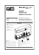

Safety instructions
The unit may only be operated at protective low voltage in
conjunction with safe electrical isola
tion. The unit may only
be repaired by the supplier.
Never touch any electronic and optical components of the sensor.
General
Contents Chapter Page
Safety instructions ................................................................................................................................................................ 22
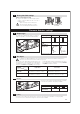
Function overview (remote control unit) ............................................................................................................................ 23
Enhanced function overview................................................................................................................................................ 24
1 Installations ............................................................................................ 24–25
2 Electrical connection .............................................................................. 25–26
3 Switch-on and initialisation............................................................................ 26
Motion detector settings 4 Programming using the remote control unit .......................................... 26–28
5 Programming using the control keys (without the remote control unit) ...... 28
6 Mechanical settings of the radar field .......................................................... 28
7 Testing the field settings .............................................................................. 29
Presence detector settings 8 Output type.................................................................................................. 29
9 Test input ...................................................................................................... 29
10 Programming using the remote control unit .......................................... 30–32
11 Programming using the control keys (without the remote control unit) ...... 32
12 Mechanical settings of the active infrared field ............................................ 32
13 Testing the field settings .............................................................................. 32
General functions 14 Manual detection .......................................................................................... 33
15 Combined outputs ........................................................................................ 33
16 Access code.................................................................................................. 33
17 Reset ..............................................................................................................33
18 Self-test ..........................................................................................................33
Overview function indications 19 LED displays ............................................................................................34–35
Reglobeam remote control unit 20 Function .................................................................................................. 35–37
21 Access code ..................................................................................................37
Field dimensions, motion detector/presence detector...................................................................................................... 38
Technical data ........................................................................................................................................................................ 39
List of coutries/Declaration of Conformity/FCC-Approval/Warranty and Liability ........................................................ 40
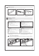
All Jupiter sensors passed the EC Type Examinations according to DIN 18650: 2005, EN 12978: 2003 and other relevant standards and
thus comply with the requirements of the European Machine Directive (98/37/EG), Appendix I. The sensors are TÜV-certified and are
thus approved as sole safety devices when used with automatic sliding doors. Risk assessment, correct installation, consideration of additional
local standards as well as observance of the required detection areas to secure hazardous areas during the opening and closing of the door fall
within the area of responsibility of the person who installs the automatic door system.
Use as a safety device according to the European Machine Directive
For Germany: The Jupiter SE with self-monitored motion
detector is well suited for doors in escape and rescue routes.
It must be installed in the direction of escape. Please note the
additional requirements from the “Richtlinie über Türen in Ret-
tungswegen” [Directive for doors in escape routes] (AutSchR: 1997).
Doors on escape routes
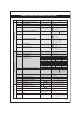
Some functions permit settings that are not in accordance with prEN 12650: 1996 / DIN 18650: 2005 or AutSchR: 1997 (Directive
for automatic sliding doors in escape and rescue routes):
Relevant for AutSchR:
Relevant for prEN 12650/ DIN18650:
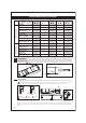
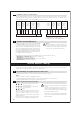
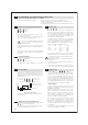
Signalization: When programming using the remote control, the two LEDs (green and red) indicate the status:
Green LED = all settings are in accordance with AutSchR and prEN 12650/ DIN 18650
Green + red LED simultaneously = some settings are not in accordance with AutSchR or prEN 12650/ DIN 18650
When programming using the control keys (without remote control) no differentiation is made with the LED indicators.
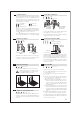
Teach-in time (presence detector chapter 10.5)
Levels 1, 5, 6, 7, 8, 9 = In acc. with prEN 12650 / DIN 18650
Levels 2, 3, 4 = Not in acc. with prEN 12650 / DIN 18650
Width of detection area (presence detector chapters 10.7)
➔
Depending on the opening width of the door
Sensitivity (presence detector chap. 10.8)
Levels 1 and 2 = In acc. with prEN 12650 / DIN 18650
Levels 3 and 4 = Not in acc. with prEN 12650 / DIN 18650
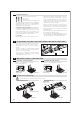
Switch output signal active/passive/OFF (chapter 10.1)
Levels 1 and 2 = In acc. with prEN 12650 / DIN 18650
Level 3 = Not in acc. with prEN 12650 / DIN 18650
Depth of detection area (presence detector ch. 10.10)
Level 1 = In acc. with prEN 12650 / DIN 18650
Levels 2 and 3 = Not in acc. with prEN 12650 / DIN 18650
Self-test (general functions chapter 18)
Levels 1 and 3 = In acc. with prEN 12650 / DIN 18650
Levels 2 and 4 = Not in acc. with prEN 12650 / DIN 18650
Switch output signal active/passive/OFF
(Motion decetor chap. 4.1)
Levels 1 and 2 = In acc. with AutSchR (for Jupiter SE)
Level 3 = Not in acc. with AutSchR
Self-test (general functions chapter 18)
Levels 1 and 2 = In acc. with AutSchR
Levels 3 and 4 = Not in acc. with AutSchR
Settings with relevance for the standards
22