TF8200 A2+ SE/TF720 A2+/TF710 A2+ Setup Manual FCC Information and Copyright This equipment has been tested and found to comply with the limits of a Class B digital device, pursuant to Part 15 of the FCC Rules. These limits are designed to provide reasonable protection against harmful interference in a residential installation.
Table of Contents Chapter 1: Introduction ............................................................ 1 1.1 Before You Start ................................................................................ 1 1.2 Package Checklist ............................................................................. 1 1.3 Motherboard Features...................................................................... 2 1.4 Rear Panel Connectors ..................................................................... 3 1.
TF8200 A2+ SE/TF720 A2+/TF710 A2+ CHAPTER 1: INTRODUCTION 1.1 BEFORE YOU START Thank you for choosing our product. Before you start installing the motherboard, please make sure you follow the instructions below: Prepare a dry and stable working environment with sufficient lighting. 1.2 Always disconnect the computer from power outlet before operation.
Motherboard Manual 1.3 MOTHERBOARD FEATURES TF8200 A2+ SE CPU FSB Chipset TF720 A2+/TF710 A2+ Socket AM2+ Socket AM2+ AMD Athlon 64 / Athlon 64 FX / Athlon 64 x2 / AMD Athlon 64 / Athlon 64 FX / Athlon 64 x2 / Sempron / Phenom processors Sempron / Phenom processors AMD 64 Architecture enables 32 and 64 bit AMD 64 Architecture enables 32 and 64 bit computing computing Supports Hyper Transport 3.0 and PowerNow Supports Hyper Transport 3.0 and PowerNow Support HyperTransport 3.
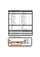
TF8200 A2+ SE/TF720 A2+/TF710 A2+ TF8200 A2+ SE Slots On Board Connector Back Panel I/O Board Size TF720 A2+/TF710 A2+ PCI slot x3 PCI slot PCI Express Gen2 x16 slot x1 PCI Express Gen2 x16 slot x1 PCI Express x1 slot x2 PCI Express x1 slot x2 Floppy connector x1 Floppy connector x1 Printer Port connector x1 Printer Port connector x1 IDE Connector x1 IDE Connector x1 SATA Connector x6 SATA Connector x6 Front Panel Connector x1 Front Panel Connector x1 Front Audio Connecto
Motherboard Manual 1.
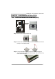
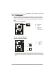
TF8200 A2+ SE/TF720 A2+/TF710 A2+ CHAPTER 2: HARDWARE INSTALLATION 2.1 INSTALLING CENTRAL PROCESSING UNIT (CPU) Step 1: Remove the socket protection cap. Step 2: Pull the lever toward direction A from the socket and then raise the lever up to a 90-degree angle. Step 3: Look for the white triangle on socket, and the gold triangle on CPU should point towards this white triangle. The CPU will fit only in the correct orientation.
Motherboard Manual Step 4: Hold the CPU down firmly, and then close the lever toward direct B to complete the installation. Step 5: Put the CPU Fan on the CPU and buckle it. Connect the CPU FAN power cable to the JCFAN1. This completes the installation. Note: Please update the BIOS to the latest version while using AM2+ CPUs. Due to the latest CPU transition, you may encounter the situation that the new system failed to boot while using new AM2+ CPUs.
TF8200 A2+ SE/TF720 A2+/TF710 A2+ 2.2 FAN HEADERS These fan headers support cooling-fans built in the computer. The fan cable and connector may be different according to the fan manufacturer. Connect the fan cable to the connector while matching the black wire to pin#1.
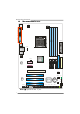
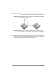
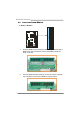
Motherboard Manual 2.3 INSTALLING SYSTEM MEMORY 8 DIMMB2 DIMMB1 DIMMA2 DIMMA1 A. Memory Modules 1. Unlock a DIMM slot by pressing the retaining clips outward. Align a DIMM on the slot such that the notch on the DIMM matches the break on the Slot. 2. Insert the DIMM vertically and firmly into the slot until the retaining chip snap back in place and the DIMM is properly seated.
TF8200 A2+ SE/TF720 A2+/TF710 A2+ B. Memory Capacity DIMM Socket Location DDR2 Module DIMMA1 256MB/512MB/1GB/2GB/4GB DIMMB1 256MB/512MB/1GB/2GB/4GB DIMMA2 256MB/512MB/1GB/2GB/4GB DIMMB2 256MB/512MB/1GB/2GB/4GB Total Memory Size Max is 16GB. C. Dual Channel Memory installation To trigger the Dual Channel function of the motherboard, the memory module must meet the following requirements: Install memory module of the same density in pairs, shown in the following table.
Motherboard Manual 2.4 CONNECTORS AND SLOTS FDD1: Floppy Disk Connector The motherboard provides a standard floppy disk connector that supports 360K, 720K, 1.2M, 1.44M and 2.88M floppy disk types. This connector supports the provided floppy drive ribbon cables. 34 33 2 1 IDE1: Hard Disk Connector The motherboard has a 32-bit Enhanced IDE Controller that provides PIO Mode 0~4, Bus Master, and Ultra DMA 33/66/100/133 functionality.
TF8200 A2+ SE/TF720 A2+/TF710 A2+ PCI-EX1: PCI-Express Gen2 x16 Slot - PCI-Express 2.0 compliant. Maximum theoretical realized bandwidth of 8GB/s simultaneously per direction, for an aggregate of 16GB/s totally. PCI-Express Gen2 supports a raw bit-rate of 5.0Gb/s on the data pins. 2X bandwidth over the PCI-Express 1.1 architecture. PCI-EX1_1/PCI-EX1_2: PCI-Express x1 Slots - PCI-Express 1.1 compliant. Data transfer bandwidth up to 250MB/s per direction; 500MB/s in total.
Motherboard Manual CHAPTER 3: HEADERS & JUMPERS SETUP 3.1 HOW TO SETUP JUMPERS The illustration shows how to set up jumpers. When the jumper cap is placed on pins, the jumper is “close”, if not, that means the jumper is “open”. Pin opened 3.2 Pin closed Pin1-2 closed DETAIL SETTINGS JPANEL1: Front Panel Header This 16-pin connector includes Power-on, Reset, HDD LED, Power LED, and speaker connection. It allows user to connect the PC case’s front panel switch functions.
TF8200 A2+ SE/TF720 A2+/TF710 A2+ JATXPWR1: ATX Power Source Connector This connector allows user to connect 24-pin power connector on the ATX power supply. 12 24 1 13 Pin Assignment Pin Assignment 13 14 15 16 17 18 19 20 21 22 23 24 +3.3V -12V Ground PS_ON Ground Ground Ground NC +5V +5V +5V Ground 1 2 3 4 5 6 7 8 9 10 11 12 +3.3V +3.3V Ground +5V Ground +5V Ground PW_OK Standby Voltage+5V +12V +12V +3.
Motherboard Manual JUSB2~JUSB5: Headers for USB 2.0 Ports at Front Panel This header allows user to connect additional USB cable on the PC front panel, and also can be connected with internal USB devices, like USB card reader. JUSB2 JUSB3 JUSB4 JUSB5 2 1 10 9 Pin 1 2 3 4 5 6 7 8 9 10 Assignment +5V (fused) +5V (fused) USBUSBUSB+ USB+ Ground Ground Key NC JAUDIOF1: Front Panel Audio Header This header allows user to connect the front audio output cable with the PC front panel.
TF8200 A2+ SE/TF720 A2+/TF710 A2+ JCDIN1: CD-ROM Audio-in Connector This connector allows user to connect the audio source from the variaty devices, like CD-ROM, DVD-ROM, PCI sound card, PCI TV turner card etc. 1 4 Assignment Left Channel Input Ground Ground Right Channel Input Pin 1 2 3 4 JCMOS1: Clear CMOS Header By placing the jumper on pin2-3, it allows user to restore the BIOS safe setting and the CMOS data, please carefully follow the procedures to avoid damaging the motherboard.
Motherboard Manual JPRNT1: Printer Port Connector This header allows you to connector printer on the PC. 2 1 Pin 1 2 3 4 5 6 7 8 9 10 11 12 13 25 Assignment Pin -Strobe -ALF Data 0 -Error Data 1 -Init Data 2 -Scltin Data 3 Ground Data 4 Ground Data 5 14 15 16 17 18 19 20 21 22 23 24 25 26 Assignment Ground Data 6 Ground Data 7 Ground -ACK Ground Busy Ground PE Ground SCLT Key JCOM2: Serial port Connector The motherboard has a Serial Port Connector for connecting RS-232 Port.
TF8200 A2+ SE/TF720 A2+/TF710 A2+ SATA1~SATA6: Serial ATA Connectors SATA1 SATA4 SATA2 SATA5 SATA3 SATA6 The motherboard has a PCI to SATA Controller with 6 channels SATA interface, it satisfies the SATA 2.0 spec and with transfer rate of 3.0Gb/s. 7 4 Pin 1 2 3 4 5 6 7 Assignment Ground TX+ TXGround RXRX+ Ground 1 Note: Due to the chipset's specification, SATA5 and SATA6 do not support SATA mode, only support AHCI+RAID mode.
Motherboard Manual On-Board Buttons There are 2 on-board buttons. RSTSW1 PWRSW1 PWRSW1: This is an on-board Power Switch button. RSTSW1: This is an on-board Reset button. JSPDIF_OUT1: Digital Audio-out Connector This connector allows user to connect the PCI bracket SPDIF output header. Pin 1 2 3 1 Assignment +5V SPDIF_OUT Ground 3 J1: Auxiliary Power for Graphics This connector is an auxiliary power connection for graphics cards.
TF8200 A2+ SE/TF720 A2+/TF710 A2+ JUSBPW1/JUSBPW2: Power Source Headers for USB Ports Pin 1-2 Close: JUSBPW1: +5V for USB ports at JUSB1/JUSBLAN1. JUSBPW2: +5V for USB ports at front panel (JUSB2~JUSB5). Pin 2-3 Close: JUSBPW1: +5V STB for USB ports at JUSB1/JUSBLAN1. JUSBPW2: +5V STB for USB ports at front panel (JUSB2~JUSB5). 1 JUSBPW1 1 3 3 Pin 1-2 close 1 JUSBPW2 3 1 3 Pin 2-3 close JPSPW1: Power Source Header for PS/2 Keyboard and Mouse 1 3 1 3 Pin 1-2 close +5V for PS/2 keyboard and mouse.
Motherboard Manual CHAPTER 4: NVIDIA RAID FUNCTIONS 4.1 OPERATION SYSTEM Supports Windows XP and Windows VISTA. 4.2 RAID ARRAYS NVRAID supports the following types of RAID arrays: RAID 0: RAID 0 defines a disk striping scheme that improves disk read and write times for many applications. RAID 1: RAID 1 defines techniques for mirroring data. RAID 0+1: RAID 0+1 combines the techniques used in RAID 0 and RAID 1. RAID 5: RAID 5 provides fault tolerance and better utilization of disk capacity. 4.
TF8200 A2+ SE/TF720 A2+/TF710 A2+ RAID 1: Every read and write is actually carried out in parallel across 2 disk drives in a RAID 1 array system. The mirrored (backup) copy of the data can reside on the same disk or on a second redundant drive in the array. RAID 1 provides a hot-standby copy of data if the active volume or drive is corrupted or becomes unavailable because of a hardware failure.
Motherboard Manual RAID 0+1: RAID 0 drives can be mirrored using RAID 1 techniques. Resulting in a RAID 0+1 solution for improved performance plus resiliency. Features and Benefits Drives: Minimum 4, and maximum is 6 or 8, depending on the platform. Benefits: Optimizes for both fault tolerance and performance, allowing for automatic redundancy. May be simultaneously used with other RAID levels in an array, and allows for spare disks.
TF8200 A2+ SE/TF720 A2+/TF710 A2+ RAID 5: RAID 5 stripes both data and parity information across three or more drives. It writes data and parity blocks across all the drives in the array. Fault tolerance is maintained by ensuring that the parity information for any given block of data is placed on a different drive from those used to store the data itself. Features and Benefits Drives: Minimum 3. Uses: RAID 5 is recommended for transaction processing and general purpose service.
Motherboard Manual CHAPTER 5: T-SERIES BIOS & SOFTWARE 5.1 T-SERIES BIOS T-Series BIOS Features Overclocking Navigator Engine (O.N.E.) Memory Integration Test (M.I.T., under Overclock Navigator Engine) BIO-Flasher: Update BIOS file from USB Flash Drive or FDD Self Recovery System (S.R.S) Smart Fan Function CMOS Reloading Program !! WARNING !! For better system performance, the BIOS firmware is being continuously updated.
TF8200 A2+ SE/TF720 A2+/TF710 A2+ Manual Overclock System (M.O.S.) MOS is designed for experienced overclock users. It allows users to customize personal overclock settings. Main Advanced PCIPnP BIOS SETUP UTILITY Boot Chipset T-Series T-Series Settings Exit Options WARNING: Setting wrong values in below sections may cause system to malfunction.
Motherboard Manual Processor Frequency Miltiplier This function allows you to adjust the frequency ratio of CPU. SB to K8(CPU) Freq Auto This function allows you to set the SB to K8 frequency. SB to K8(CPU) LinkWidth This function allows you to choose the SB to K8 link width. Memory Clock Mode This function allows you to control the Memory Clock. MCP PCI-Express Frequency, MHz It helps to increase VGA card performance.
TF8200 A2+ SE/TF720 A2+/TF710 A2+ V6 Tech Engine This engine will make a good over-clock performance. Main Advanced PCIPnP BIOS SETUP UTILITY Boot Chipset T-Series T-Series Settings Exit Options WARNING: Setting wrong values in below sections may cause system to malfunction.
Motherboard Manual Notices: 1. Not all types of AMD CPU perform above overclock setting ideally; the difference will be based on the selected CPU model. B. Memory Integration Test (M.I.T.) This function is under “Overclocking Navigator Engine” item. MIT allows users to test memory compatibilities, and no extra devices or software are needed. Step 1 The default setting under this item is “Disabled”; the condition parameter should be changed to “Enable” to proceed this test.
TF8200 A2+ SE/TF720 A2+/TF710 A2+ C. BIO-Flasher BIO-Flasher is a BIOS flashing utility providing you an easy and simple way to update your BIOS via USB pen drive or floppy disk. The BIO-Flasher is built in the BIOS chip. To enter the utility, press during the Power-On Self Tests (POST) procedure while booting up. Updating BIOS with BIO-Flasher 1. Go to the website to download the latest BIOS file for the motherboard. 2. Then, save the BIOS file into a USB pen drive or a floppy disk. 3.
Motherboard Manual D. Self Recovery System (S.R.S.) This function can’t be seen under BIOS setup; and is always on whenever the system starts up. However, it can prevent system hang-up due to inappropriate overclock actions. When the system hangs up, S.R.S. will automatically log in the default BIOS setting, and all overclock settings will be re-configured. E. Smart Fan Function Smart Fan Function is under “Smart Fan Configuration” in “Advanced Menu”.
TF8200 A2+ SE/TF720 A2+/TF710 A2+ Smart Fan Calibration Choose this item and then the BIOS will automatically test and detect the CPU/System fan functions and show CPU/System fan speed. Control Mode This item provides several operation modes of the fan. Fan Ctrl OFF(℃) If the CPU/System temperature is lower than the set value, the CPU/ System fan will turn off. The range is from 0~127, with an interval of 1.
Motherboard Manual 5.2 T-SERIES SOFTWARE Installing T-Series Software 1. Insert the Setup CD to the optical drive. The drivers installation program would appear if the Auto-run function has been enabled. 2. Select Software Installation, and then click on the respective software title. 3. Follow the on-screen instructions to complete the installation.
TF8200 A2+ SE/TF720 A2+/TF710 A2+ Over Clock Panel Restore Default Settings AUTO Over-Clock V3/V6/V9 Engine Real-time Ove r-clock Manual Adjust CPU Clock Test & Apply Manual Setting s AUTO User can click this button and the utility will set the best and stable performance and frequency automatically. A warning dialog as below will show up to notify you that the system may become unstable, click on “OK” to continue.
Motherboard Manual Then the utility will execute a series of testing until system fail. Then system will do fail-safe reboot by using Watchdog function. After reboot, launch the utility again and the utility will load the previously verified best and stable frequency. V3 / V6 / V9 Provide user the ability to do real-time over-clock adjustment. For beginners in over-clock field, this is a powerful feature to increase system performance. V3 Engine This engine will make a good over-clock performance.
TF8200 A2+ SE/TF720 A2+/TF710 A2+ Over Voltage Panel Manual Adjust CPU/Memo ry/Chipset/FSB Voltage CPU Voltage This function allows user to adjust CPU voltage. or “-“ to decrease the CPU voltage. Click on “+” to increase Memory Voltage This function allows user to adjust Memory voltage. increase or “-“ to decrease the Memory voltage. Click on “+” to Chip Voltage This function allows user to adjust Chipset voltage. increase or “-“ to decrease the Chipset voltage.
Motherboard Manual About Panel In this panel, you can get model name and other system information that may related to over-clocking. You can also get the version number of this software. Note Because the Over Clock and Over Voltage features are controlled by several separate chipset, the utility divides these features to separate panels. If one chipset is not on board, the correlative button in Main panel will be disabled, but it will not interfere with other panels’ functions.
TF8200 A2+ SE/TF720 A2+/TF710 A2+ eHot-Line (Optional) eHot-Line is a convenient utility that helps you to contact with our Tech-Support system. This utility will collect the system information which is useful for analyzing the problem you may have encountered, and then send these information to our tech-support department to help you fix the problem. Before you use this utility, please set Outlook Express as your default e-mail client application program.
Motherboard Manual Enter the file name and then click “Save”. Your system information will be saved to a .txt file. Open the saved .txt file, you will see your system information including motherboard/BIOS/CPU/video/ device/OS information. This information is also concluded in the sent mail. We will not share customer’s data with any other third parties, so please feel free to provide your system information while using eHot-Line service.
TF8200 A2+ SE/TF720 A2+/TF710 A2+ BIOS Update BIOS Update is a convenient utility which allows you to update your motherboard BIOS under Windows system. AWARD BIOS Show current BIOS information AMI BIOS Clear CMOS function (Only for AWARD BIOS) Save current BIOS to a .bin file Update BIOS with a BIOS file Once click on this button, the saving dialog will show. Choose the position to save file and enter file name.
Motherboard Manual Before doing this, please download the proper BIOS file from the website. For AWARD BIOS, update BIOS procedure should be run with Clear CMOS function, so please check on Clear CMOS first. Then click Update BIOS button, a dialog will show for asking you backup current BIOS. Click Yes for BIOS backup and refer to the Backup BIOS procedure; or click No to skip this procedure.
TF8200 A2+ SE/TF720 A2+/TF710 A2+ CHAPTER 6: USEFUL HELP 6.1 DRIVER INSTALLATION NOTE After you installed your operating system, please insert the Fully Setup Driver CD into your optical drive and install the driver for better system performance. You will see the following window after you insert the CD The setup guide will auto detect your motherboard and operating system. Note: If this window didn’t show up after you insert the Driver CD, please use file browser to locate and execute the file SETUP.
Motherboard Manual 6.2 EXTRA INFORMATION CPU Overheated If the system shutdown automatically after power on system for seconds, that means the CPU protection function has been activated. When the CPU is over heated, the motherboard will shutdown automatically to avoid a damage of the CPU, and the system may not power on again. In this case, please double check: 1. The CPU cooler surface is placed evenly with the CPU surface. 2. CPU fan is rotated normally. 3.
TF8200 A2+ SE/TF720 A2+/TF710 A2+ 6.3 AMI BIOS BEEP CODE Boot Block Beep Codes Number of Beeps 1 2 3 4 5 7 10 11 12 13 Description No media present. (Insert diskette in floppy drive A:) “AMIBOOT.ROM” file not found in root directory of diskette in A: Insert next diskette if multiple diskettes are used for recovery Flash Programming successful File read error No Flash EPROM detected Flash Erase error Flash Program error “AMIBOOT.
Motherboard Manual 6.4 TROUBLESHOOTING Probable 1. Solution No power to the system at all 1. Make sure power cable is Power light don’t illuminate, fan securely plugged in. inside power supply does not turn 2. Replace cable. on. 3. Contact technical support. 2. Indicator light on keyboard does not turn on. System inoperative. Keyboard lights Using even pressure on both ends of are on, power indicator lights are lit, the DIMM, press down firmly until the and hard drive is spinning.
TF8200 A2+ SE/TF720 A2+/TF710 A2+ This page is intentionally left blank 45
Motherboard Manual APPENDENCIES: SPEC IN OTHER LANGUAGE GERMAN TF8200 A2+ SE Sockel AM2+ TF720 A2+/TF710 A2+ Sockel AM2+ AMD Athlon 64 / Athlon 64 FX / Althlon 64 X2 / AMD Athlon 64 / Athlon 64 FX / Althlon 64 X2 / CPU Sempron / Phenom Prozessoren Sempron / Phenom Prozessoren Die AMD 64-Architektur unterstützt eine 32-Bit- Die AMD 64-Architektur unterstützt eine 32-Bitund 64-Bit-Datenverarbeitung und 64-Bit-Datenverarbeitung Unterstützt Hyper Transport 3.0 und PowerNow Unterstützt Hyper Transport 3.
TF8200 A2+ SE/TF720 A2+/TF710 A2+ TF8200 A2+ SE LAN TF720 A2+/TF710 A2+ Realtek RTL 8111C Realtek RTL 8111C 10 / 100 / 1000 Mb/s Auto-Negotiation 10 / 100 / 1000 Mb/s Auto-Negotiation Halb-/ Vollduplex-Funktion Halb-/ Vollduplex-Funktion ALC662 ALC662 Audio-Codec 5.1-Kanal-Audioausgabe 5.
Motherboard Manual FRANCE TF8200 A2+ SE UC Bus frontal Chipset Super E/S TF720 A2+/TF710 A2+ Socket AM2+ Socket AM2+ Processeurs AMD Athlon 64 / Athlon 64 FX / Processeurs AMD Athlon 64 / Athlon 64 FX / Althlon 64 X2 / Sempron / Phenom Althlon 64 X2 / Sempron / Phenom L'architecture AMD 64 permet le calcul 32 et 64 L'architecture AMD 64 permet le calcul 32 et 64 bits bits Prend en charge Hyper Transport 3.0 et Prend en charge Hyper Transport 3.
TF8200 A2+ SE/TF720 A2+/TF710 A2+ TF8200 A2+ SE TF720 A2+/TF710 A2+ Realtek RTL 8111C LAN Realtek RTL 8111C 10 / 100 / 1000 Mb/s négociation automatique 10 / 100 / 1000 Mb/s négociation automatique Half / Full duplex capability Half / Full duplex capability ALC662 ALC662 Codec audio Sortie audio à 5.1 voies Fentes Connecteur embarqué Sortie audio à 5.
Motherboard Manual ITALIAN TF8200 A2+ SE CPU FSB Chipset Super I/O Memoria principale Grafica For TF8200A2+ SE / TF720 A2+ Only IDE SATA II TF720 A2+/TF710 A2+ Socket AM2+ Socket AM2+ Processori AMD Athlon 64 / Athlon 64 FX / Processori AMD Athlon 64 / Athlon 64 FX / Althlon 64 X2 / Sempron / Phenom Althlon 64 X2 / Sempron / Phenom L’architettura AMD 64 abilita la L’architettura AMD 64 abilita la computazione 32 e 64 bit computazione 32 e 64 bit Supporto di Hyper Transport 3.
TF8200 A2+ SE/TF720 A2+/TF710 A2+ TF8200 A2+ SE LAN Codec audio Alloggi Connettori su scheda TF720 A2+/TF710 A2+ Realtek RTL 8111C Realtek RTL 8111C Negoziazione automatica 10 / 100 / 1000 Negoziazione automatica 10 / 100 / 1000 Mb/s Mb/s Capacità Half / Full Duplex Capacità Half / Full Duplex ALC662 ALC662 Uscita audio 5.1 canali Uscita audio 5.
Motherboard Manual SPANISH TF8200 A2+ SE CPU FSB Conjunto de chips Súper E/S Memoria principal TF720 A2+/TF710 A2+ Conector AM2+ Conector AM2+ Procesadores AMD Athlon 64 / Athlon 64 FX / Procesadores AMD Athlon 64 / Athlon 64 FX / Athlon 64 X2 / Sempron / Phenom Athlon 64 X2 / Sempron / Phenom La arquitectura AMD 64 permite el procesado de La arquitectura AMD 64 permite el procesado de 32 y 64 bits 32 y 64 bits Soporta las tecnologías Hyper Transport 3.
TF8200 A2+ SE/TF720 A2+/TF710 A2+ TF8200 A2+ SE Códecs de sonido Ranuras Conectores en placa TF720 A2+/TF710 A2+ ALC662 ALC662 Salida de sonido de 5.1 canales Salida de sonido de 5.
Motherboard Manual PORTUGUESE TF8200 A2+ SE CPU FSB Chipset TF720 A2+/TF710 A2+ Socket AM2+ Socket AM2+ Processadores AMD Athlon 64 / Athlon 64 FX / Processadores AMD Athlon 64 / Athlon 64 FX / Althlon 64 X2 / Sempron / Phenom Althlon 64 X2 / Sempron / Phenom A arquitectura AMD 64 permite uma computação A arquitectura AMD 64 permite uma computação de 32 e 64 bits de 32 e 64 bits Suporta as tecnologias Hyper Transport 3.0 e Suporta as tecnologias Hyper Transport 3.
TF8200 A2+ SE/TF720 A2+/TF710 A2+ TF8200 A2+ SE LAN Codec de som Ranhuras Conectores na placa TF720 A2+/TF710 A2+ Realtek RTL 8111C Realtek RTL 8111C Auto negociação de 10 / 100 / 1000 Mb/s Auto negociação de 10 / 100 / 1000 Mb/s Capacidade semi/full-duplex Capacidade semi/full-duplex ALC662 ALC662 Saída de áudio de 5.1 canais Saída de áudio de 5.
Motherboard Manual POLISH TF8200 A2+ SE Socket AM2+ TF720 A2+/TF710 A2+ Socket AM2+ AMD Athlon 64 / Athlon 64 FX / Althlon 64 X2 / AMD Athlon 64 / Athlon 64 FX / Althlon 64 X2 / Procesor FSB Chipset Pamięć główna Sempron / Phenom Procesory Sempron / Phenom Procesory Architektura AMD 64 umożliwia przetwarzanie Architektura AMD 64 umożliwia przetwarzanie 32 i 64 bitowe 32 i 64 bitowe Obsługa Hyper Transport 3.0 oraz PowerNow Obsługa Hyper Transport 3.0 oraz PowerNow Obsługa HyperTransport 3.
TF8200 A2+ SE/TF720 A2+/TF710 A2+ TF8200 A2+ SE Kodek dźwiękowy Gniazda Złącza wbudowane TF720 A2+/TF710 A2+ ALC662 ALC662 5.1 kanałowe wyjście audio 5.
Motherboard Manual RUSSIAN TF8200 A2+ SE CPU (центральный процессор) TF720 A2+/TF710 A2+ Гнездо AM2+ Гнездо AM2+ Процессоры AMD Athlon 64 / Athlon 64 FX / Процессоры AMD Athlon 64 / Athlon 64 FX / Althlon 64 X2 / Sempron / Phenom Althlon 64 X2 / Sempron / Phenom Архитектура AMD 64 разрешать обработка Архитектура AMD 64 разрешать обработка данных на 32 и 64 бит данных на 32 и 64 бит Поддержка Hyper Transport 3.0 и PowerNow Поддержка Hyper Transport 3.
TF8200 A2+ SE/TF720 A2+/TF710 A2+ TF8200 A2+ SE TF720 A2+/TF710 A2+ Realtek RTL 8111C Realtek RTL 8111C Локальная Автоматическое согласование 10 / 100 / Автоматическое согласование 10 / 100 / сеть 1000 Мб/с 1000 Мб/с Частичная / полная дуплексная способность Частичная / полная дуплексная способность Звуковой кодек Слоты ALC662 ALC662 Звуковая поддержка High-Definition Звуковая поддержка High-Definition 5.1канальный звуковой выход 5.
Motherboard Manual ARABIC TF8200 A2+ SE AM2+ﻡﻘﺒﺲ وﺣﺪة اﻟﻤﻌﺎﻟﺠﺔ اﻟﻤﺮآﺰﻳﺔ TF720 A2+/TF710 A2+ AM2+ﻡﻘﺒﺲ AMD Athlon 64 / Athlon 64 FX / Sempron /ﻡﻌﺎﻟﺠﺎت AMD Athlon 64 / Athlon 64 FX / Sempron /ﻡﻌﺎﻟﺠﺎت Phenom / Althlon 64 X2 Phenom / Althlon 64 X2 إﺝﺮاء اﻟﻌﻤﻠﻴﺎت اﻟﺤﺎﺳﻮﺏﻴﺔ ﺏﺴﺮﻋﺔ 32و 64ﺏﺖAMD 64ﺗﻤﻜﻦ ﺗﻘﻨﻴﺔ إﺝﺮاء اﻟﻌﻤﻠﻴﺎت اﻟﺤﺎﺳﻮﺏﻴﺔ ﺏﺴﺮﻋﺔ 32و 64ﺏﺖAMD 64ﺗﻤﻜﻦ ﺗﻘﻨﻴﺔ PowerNowو Hyper Transport 3.0ﺗﺪﻋﻢ ﺗﻘﻨﻴﺔ PowerNowو Hyper Transport 3.
TF8200 A2+ SE/TF720 A2+/TF710 A2+ TF8200 A2+ SE آﻮدﻳﻚ اﻟﺼﻮت ALC662 ALC662 ﺗﺪﻋﻢ ﺗﻘﻨﻴﺔ اﻟﺼﻮت ﻋﺎﻟﻲ اﻟﺘﻌﺮﻳﻒ ﻡﻦ ﺗﺪﻋﻢ ﺗﻘﻨﻴﺔ اﻟﺼﻮت ﻋﺎﻟﻲ اﻟﺘﻌﺮﻳﻒ ﻡﻦ ﻗﻨﻮات ﻟﺨﺮج اﻟﺼﻮت5.1 اﻟﻔﺘﺤﺎت اﻟﻤﻨﺎﻓﺬ ﻋﻠﻰ ﺳﻄﺢ اﻟﻠﻮﺣﺔ ﻡﻨﺎﻓﺬ دﺥﻞ/ﺥﺮج اﻟﻠﻮﺣﺔ اﻟﺨﻠﻔﻴﺔ ﻡﺰاﻳﺎ ﺥﺎﺹﺔ ﺣﺠﻢ اﻟﻠﻮﺣﺔ دﻋﻢ أﻥﻈﻤﺔ اﻟﺘﺸﻐﻴﻞ 61 TF720 A2+/TF710 A2+ ﻗﻨﻮات ﻟﺨﺮج اﻟﺼﻮت5.
Motherboard Manual JAPANESE TF8200 A2+ SE Socket AM2+ TF720 A2+/TF710 A2+ Socket AM2+ AMD Athlon 64 / Athlon 64 FX / Althlon 64 X2 / AMD Athlon 64 / Athlon 64 FX / Althlon 64 X2 / Sempron / Phenom プロセッサ CPU FSB Sempron / Phenom プロセッサ AMD 64アーキテクチャでは、32ビットと64ビット計 AMD 64アーキテクチャでは、32ビットと64ビット計 算が可能です 算が可能です ハイパートランスポート3.0とクールアンドクワイア ハイパートランスポート3.0とクールアンドクワイア ットをサポートします ットをサポートします 5.2 GT/sのバンド幅までハイパートランスポート3.0 5.2 GT/sのバンド幅までハイパートランスポート3.
TF8200 A2+ SE/TF720 A2+/TF710 A2+ TF8200 A2+ SE サウンド Codec スロット オンボードコ ネクタ 背面パネル I/O TF720 A2+/TF710 A2+ ALC662 ALC662 ハイデフィニションオーディオのサポート ハイデフィニションオーディオのサポート 5.1 チャンネルオーディオアウト 5.